Overview
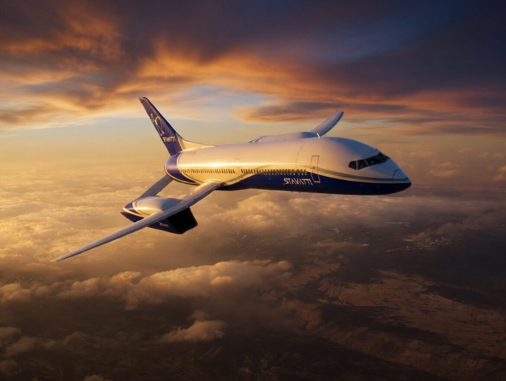
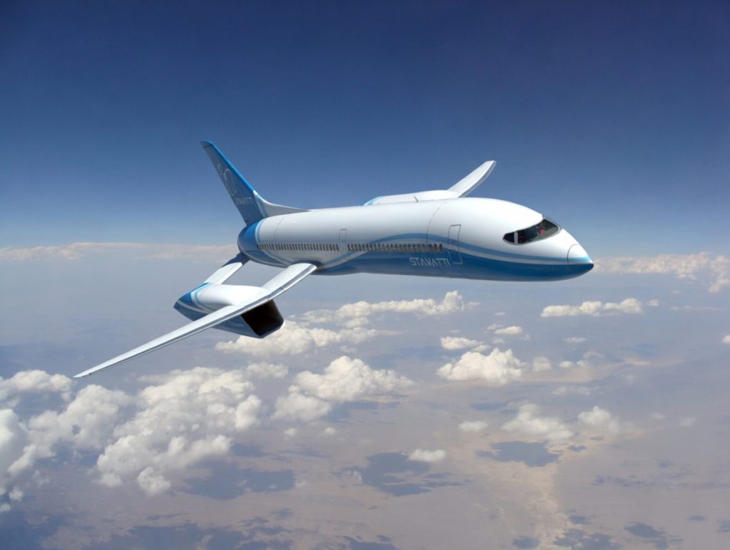
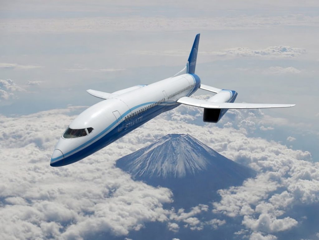
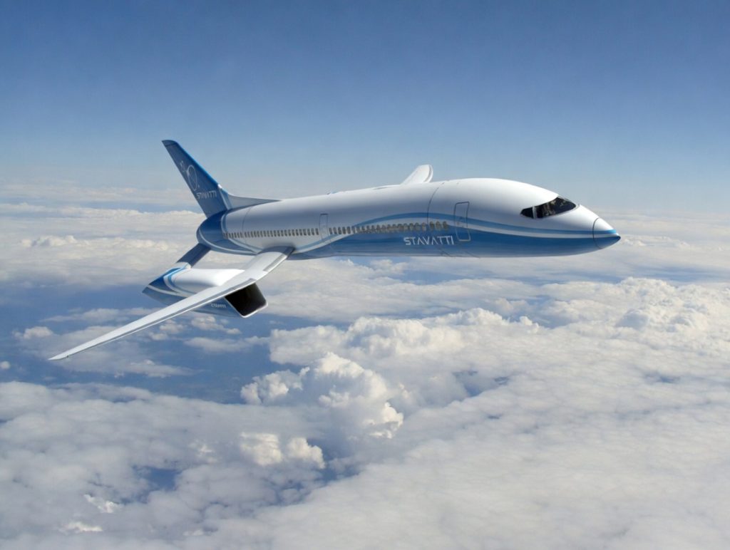
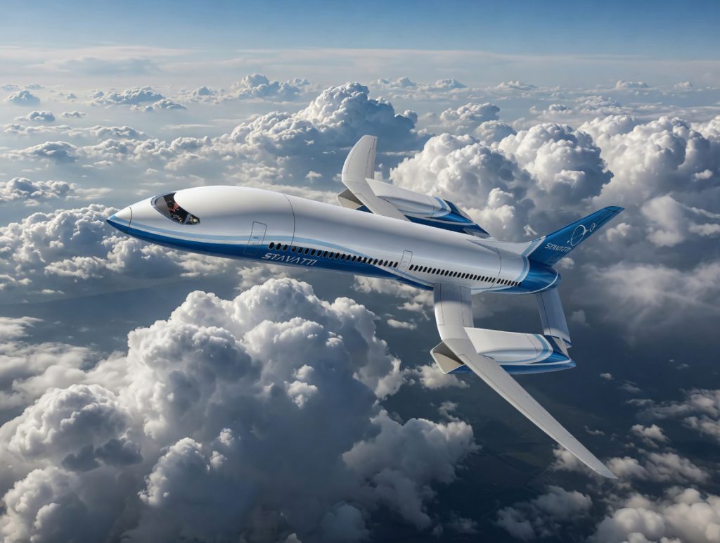
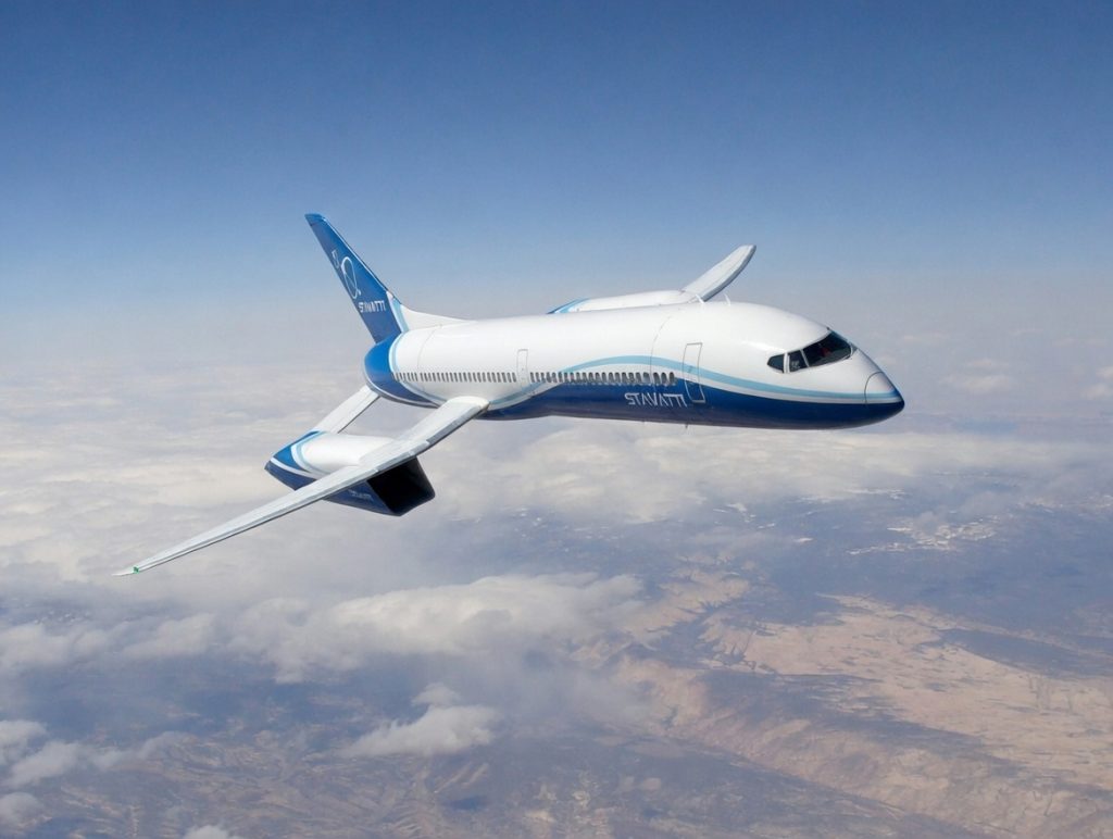
The SM-920 is a revolutionary twin engine single aisle commercial airliner that will set a new standard for efficiency, performance, eloquence and style. It is the first airliner to benefit from an all new configuration in the last 50 years and is more aerodynamically refined and optimized than any other aircraft in the industry. With its distinguished style, the SM-920 will carry up to 204 passengers at near sonic speeds with unmatched economy, comfort and low environmental impact.
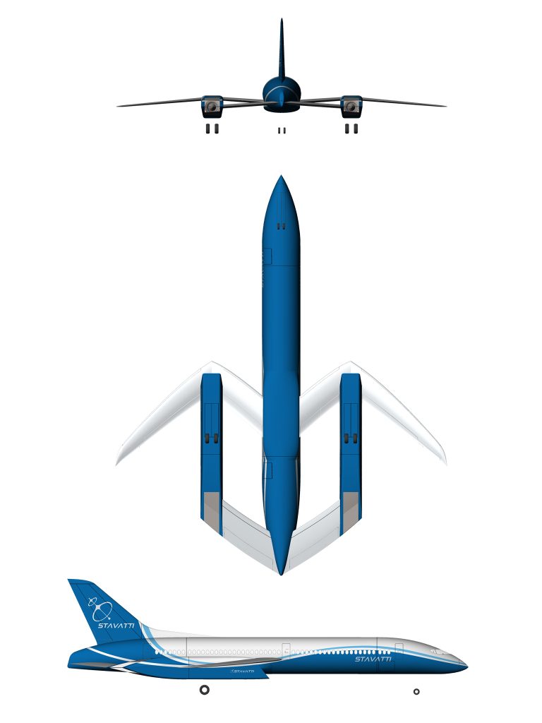
The SM-920 configuration combines a high aspect ratio M wing optimized for transonic flight with twin engines encased in novel nacelles that incorporate variable geometry air intakes and exhaust nozzles and serve as an end junction to the horizontal stabilizer. With a single vertical stabilizer, the SM-920 has a highly swept wing and a high finness ratio, speed optimized fuselage. A modular airplane, the SM-920 will be constructed primarily from aluminum lithium foam metal sandwich structures that combine aluminum lithium and titanium skins with a laser welded aluminum foam metal core. Featuring aluminum lithium, scandium aluminum and titanium construction, the SM-920 exploits the advantages of proven advanced aluminums and superalloys.

Initial production SM-920s will be powered by twin P&W Geared turbofans or CFM LEAP turbofans while SM-920s produced after 2035 may feature new design, next generation NeoThrust E750-AFT-360 Aft Fan Turbofan (AFT) engines for greater cruise efficiency in the transonic regime. Powerplants featured in the prototype engineering design phase include the PW1133G-JM High Bypass Ratio Geared Turbofan and the LEAP 1A32 High Bypass Ratio Turbofan.
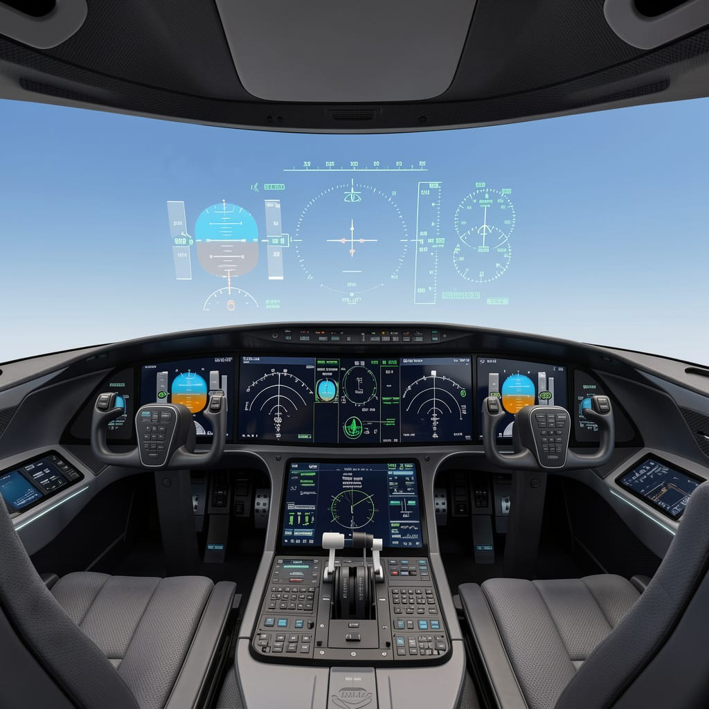
Married to a proprietary noise damping exhaust duct with variable geometry, 2D thrust vectoring exhaust nozzle with integral thrust reversing, the SM-920 will benefit from the lowest noise signature in its class while providing shorter takeoff and landing distances. With a fully integrated avionics and sensors suite, the SM-920 will benefit from a next generation cockpit that incorporates a dynamic, monolithic active flat panel display with a wide area HUD as the primary flight display instrument. A power-by-wire aircraft, the SM-920 will benefit from an advanced four channel digital electromechanical flight control system. Aircraft ailerons, flaps, slats, spoilers, elevators, rudders and landing gear are electromechanically actuated.
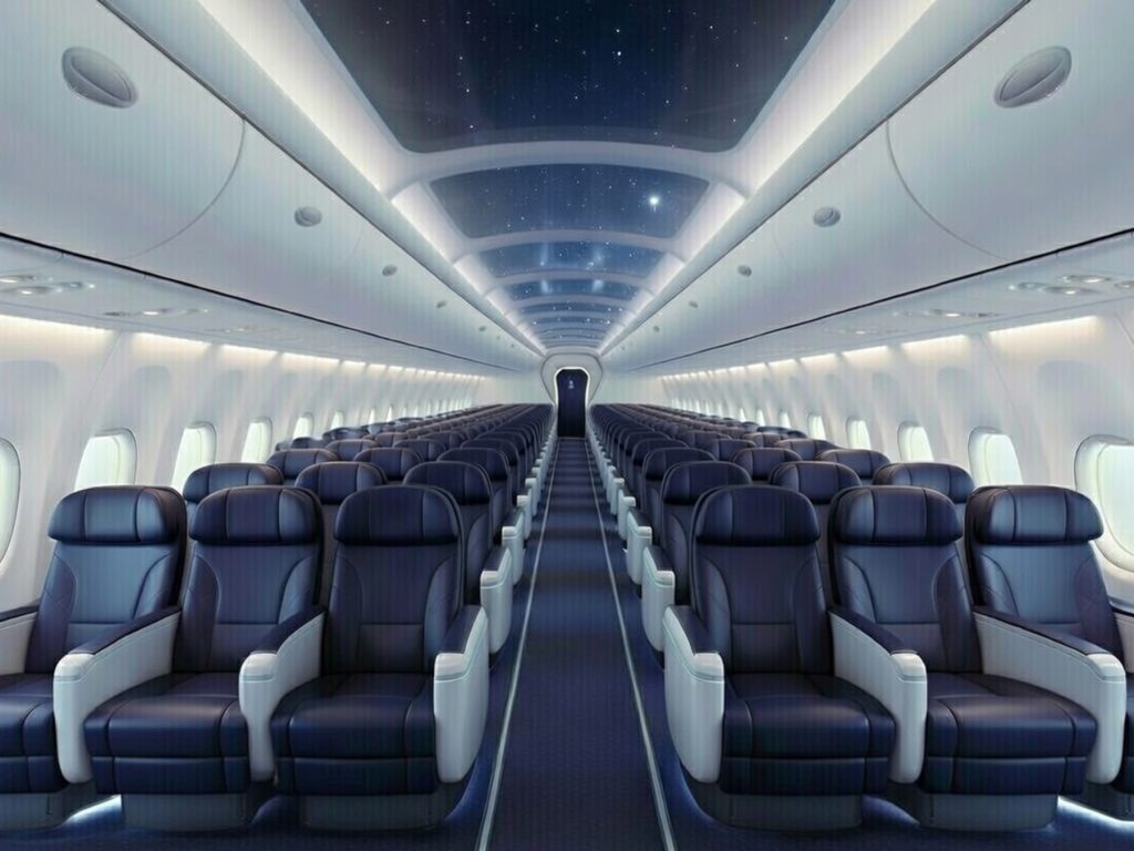
With a cruise speed of 0.95 Mach and a range of over 4,000 nm the SM-920 will offer lower operating costs than either the 737 Max or the A320neo. With a flight crew of two and three to six flight attendants, the SM-920 can carry 180 passengers in a two class first/economy arrangement or 204 passengers in an all economy configuration. Offering a wider cabin than either the 737 or A320, the SM-920 will offer two rows of three 19 in wide economy seats in a six abreast configuration with a 30 in wide center aisle. Maximum center aisle cabin height is 90 in with standard 32 in Economy Class seat pitch. Featuring four large footprint lavatories and both a forward and aft galley the SM-920 cabin will benefit from a cabin air pressurization system with integrated UV air cleansing and purification system with AHPCO technology.
Designed to serve as a successor to the Boeing 737, Airbus A320 and Airbus A321 families of aircraft, the SM-920 is an original design conceived by Stavatti founder Christopher R. Beskar and is protected by USPTO Design Patent Number US D1,116,977 S. The SM-920 will be Type Certified as a Transport Category aircraft under Federal Aviation Administration (FAA) Federal Aviation Regulations (FAR) Part 25-Airworthiness Standards for Transport Category Airplanes (14 CFR Part 25).
Accommodation
The SM-920 has a crew of two seated side-byside on the flight deck. Optional seating for two additional crew members on forward facing folding seats. Optional overhead cabin bunk to serve as a crewmember rest station. Folding seats for cabin attendants. Single Aisle main cabin has seating for up to 204 passengers with locations at the front and the rear of the cabin for galleys, lavatories and closets. Lavatories will accommodate wheel chairs while aft galley is a full kitchen suitable for fresh meal preparation. A total of six plug type cabin doors for passengers and service access including two forward doors, two mid fuselage doors and two aft fuselage doors. The aircraft cabin will benefit from an independent air pressurization system with integrated UV air cleansing and purification system with AHPCO technology.
The forward cabin door may be equipped with an Airstair. Doors measure 72 in high and 36 in wide. Emergency overwing exits are located on each side of the aircraft. The cabin has a total interior volume of 9,399 cu ft and a cabin floor area of 1,519 sq ft. One underfloor cargo compartment and baggage hold with a total volume of 2,104 cu ft. The cargo compartment is designed to carry 10 LD3-45 containers and features a mechanized cargo loading system.
A typical All-Economy class layout has 34 rows of seats in six abreast economy class with 32 in pitch for a total of 204 seats. Typical two-class cabin First-Economy layout has 12 seats in four abreast first class with 60 in pitch and 168 seats in six abreast economy class with 32 in pitch for a total of 180 seats. An alternative two-class Business-Economy configuration has 25 seats in five abreast business class with 38 in pitch and 162 seats in six abreast economy class with 32 in pitch for a total of 187 seats. An all-Business Class layout has 27 rows of seats in five abreast business class with 38 in pitch for a total of 135 seats. A Premium Economy Class layout has 27 rows of seats in six abreast economy class with 38 in pitch for a total of 162 seats. The SM-920 may feature a fuselage plug to stretch the aircraft to a 240 seat SM-920-240 configuration featuring 40 rows of six abreast economy class seats with 32 in pitch.
Economy class configurations enable a 30 in wide center aisle permitting ease-of-transit throughout the cabin and quicker turn-around times. The fuselage cross section is significantly greater than competitor single aisle aircraft, permitting the use of wider triple seats to provide a higher standard of passenger comfort throughout all classes.
Cabin overhead storage lockers provide 3.18 cu ft per seat with 180 seats and 3.0 cu ft per seat with 204 seats. Passenger cabin windows are of large area oval type with a viewing area measuring 18 in high and 12 in wide. Windows feature auto-tint with shades for individual control.
Powerplants
The SM-920 may be powered by twin P&W geared turbofans or CFM LEAP turbofans while SM-920s produced after 2035 may feature new design, next generation NeoThrust E750-AFT-360 Aft Fan Turbofan (AFT) engines for greater cruise efficiency in the transonic regime. Powerplants consideration to power the SM-920 through prototype engineering development, flight testing, certification and initial production include the PW1133G-JM High Bypass Ratio Geared Turbofan delivering 33,100 lbs of static thrust at sea level as well as the LEAP 1A32 High Bypass Ratio Turbofan delivering 32,900 lbs of static thrust at sea level. Powering later production models, the E750-AFT-360 is a new design High Bypass Ratio Aft Fan Turbofan under development by the NeoThrust division of Stavatti to produce up to 36,000 lbs of static thrust at sea level.
Powerplants are housed within an engine nacelle featuring a limited variable geometry air intake for greater pressure recoveries at high Mach numbers and a variable geometry exhaust nozzle with two dimensional thrust vectoring and thrust reversing. Borrowing supersonic fighter geometry, the SM- 920s air intake system is sized for large mass flow powerplants and optimized to ensure that high bypass ratio engines can operate more efficiency at transonic and near sonic speeds. Serving as a structural member that joins the aircraft wing and horizontal tail, the SM-920 inlets are mounted below the main wing to ensure continuous clean airflow at all angles of attack. To improve crosswind landing ability and provide a wide-stance, the aircraft’s main landing gear are mounted to and upon retraction housed within the engine nacelle.
The SM-920 may be powered by two Pratt & Whitney PW1133G-JM High Bypass Ratio Geared Turbofans delivering 33,110 lbs of static thrust at sea level each for a total combined thrust of 66,220 lbs. Specific fuel consumption at maximum takeoff thrust is approximately 0.302 lbs/h/lbs st. The result of a successful collaboration with MTU Aero Engines, the PW1133G-JM benefits from the PurePower scaled engine core to achieve double digit improvements in fuel consumption, up to a 75% reduction in noise and up to 50% reduction in emissions including NOx.
Inspired by the development of the Advanced Ducted Propulsor (ADP) and subsequent PW8000, the PW1100G-JM was certified in December 2014 with the PW1133G-JM variant entering into service in October 2015. The PW1133G-JM powers the Airbus A321neo while other members of the PurePower engine family power the Airbus A220 and Airbus A320neo. The PurePower PW1200G and PW1400G were selected to power the Mitsubishi Regional Jet and Yakolev MC-21 respectively.
The PW1133G-JM features a single stage, 81 in diameter bird strike resistant hybrid metallic advanced fan blade driven by a Fan Drive Gear System (FDGS).
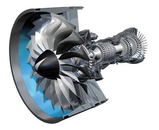
The FDGS has 13 major parts, is more than 99.5% mechanically efficient and is projected to have a 20 year TBO. With a mass flow of 1,319 lbs/sec and a fan bypass ratio of 12.5:1 the PW1133G-JM delivers an overall pressure ratio of 40.0. The engine has a total of 3 low pressure compressor stages, 8 advanced technology high pressure compressor stages, a Talon® X combustor, 2 high pressure turbine stages and 3 low pressure turbine stages. The powerplant has a Turbine Inlet Temperature (TIT) of 1,982° F and an overall dry weight of 6,300 lbs.
The SM-920 may also be powered by two CFM International LEAP-1A32 High Bypass Ratio turbofans delivering 32,900 lbs of static thrust at sea level each for a total combined thrust of 65,800 lbs. Specific fuel consumption at maximum takeoff thrust is 0.323 lbs/h/lbs st. A successor to the CFM56 family, the LEAP engine is produced by CFM International: a joint venture between GEAE and Safran Aircraft Engines. Offering up to a 15% reduction in fuel consumption and carbon dioxide emissions over previous generation engines, the LEAP series entered service in 2016 following a development program that began in 2010. The LEAP family of engines delivers up to 35,000 lbs of thrust and was selected to power the A320neo, the 737 MAX and the Comac C919 families of aircraft. Certified in 2014, the LEAP-1A32 is compliant with future Chapter 14 noise regulations, has up to a 50% margin on NOx emissions when compared to the CAEP/6 standard and has maintenance costs comparable to standard CFM56 engines.
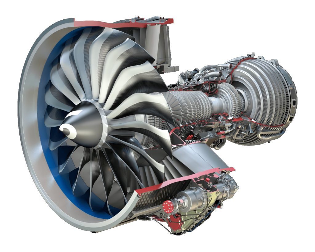
The LEAP-1A32 offers a single stage, 78 in diameter, 3-D woven carbon fiber composite fan that delivers a mass flow of 965 lbs/sec with a fan bypass ratio of 10.0. With an overall engine pressure ratio of 52.0 the engine has a total of 13 compressor stages including 3 booster stages and 10 high pressure compressor stages. The pressure ratio on the high pressure compressor is 22 to 1. The compressor and fan are driven by 2 high pressure turbines and 7 low pressure turbines. With a TAPS II lean burning LEAP combustor, the engine has a maximum Turbine Inlet Temperature (TIT) of 1,949° F and FADEC IV controls. With a TBO of approximately 20,000 hours, the LEAP-1A32 is regarded as having the potential to be one of the finest aircraft engines ever produced.
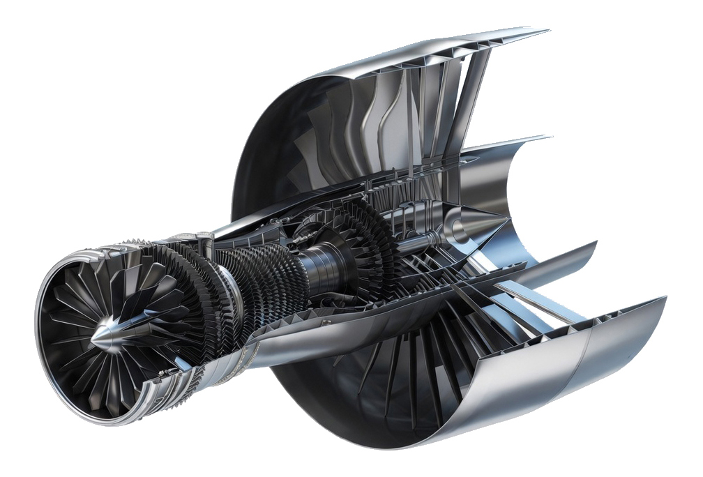
Future SM-920 production aircraft will be powered by a new design Stavatti-NeoThrust E750-AFT-360 Aft Fan Turbofan as an optional secondary powerplant. This engine is being designed specifically for the SM-920 by the NeoThrust™ division of Stavatti and is expected to enter service within 5 years of the launch of SM-920 production. This powerplant is designed to produce 36,000 lbs thrust at sea level with a specific fuel consumption of 0.284 lbs/h/lbs st at maximum takeoff thrust.
The E750-AFT- 360 is derived from the E750 afterburning turbofan and will be produced by Stavatti NeoThrust. The E750-AFT-360 marries the basic E750 turbojet design with an aft fan to result in a higher-bypass turbofan. Inspired by historical aft fan turbofans including the CJ-805-23 and CF700, the E750-AFT-360 builds upon a proven architecture to achieve an optimized powerplant solution for future Stavatti commercial airliners including the SM-920.
With a core mass flow of 152 lbs/sec and an aft fan mass flow of 814 lbs/sec, E750-AFT-360 mass flow is 966 lbs/sec at sea level maximum thrust. With a low pressure compressor pressure ratio of 4.66, a high pressure compressor pressure ratio of 6.44 and an aft fan pressure ratio of 1.75, the maximum overall pressure ratio of the powerplant is 52.5. Powerplant overall bypass ratio is 5.36. For enhanced efficiency, the powerplant benefits from advanced materials including Non-Carbothermic Titanium Diboride (TiB2) cermet materials. TiB2 is used throughout the engine including the engine inlet and fan, compressor, combustormodule, turbines and in bearings. These materials enable higher combustion and Turbine Inlet Temperatures (TITs) while reducing mechanical friction resulting in overall improvements in powerplant thermodynamic and mechanical efficiency. The E750-AFT-360 will be approximately 33.7% more fuel efficient than the CFM56-7B27/3.
A two shaft aft fan turbofan, the E750-AFT-360 has six modules plus an accessories gearbox. The forward fan and low pressure compressor module is a three-stage, three rotor unit with a long chord blisk fan with 17 variable inlet guide vanes. The fan module is mounted to the engine mid-frame which houses the forward engine mounts, eight support struts and the internal bypass inlet. The compressor module consists of an eight stage, dual rotor counter-rotating axial flow high pressure compressor with three rows of variable stators. The combustion chamber module consists of a high temperature annular combustor with two ignitors and 18 fuel nozzles.
The turbine module includes a single high pressure turbine to drive the high pressure compressor and a single low pressure turbine to drive the low pressure compressor. The turbines are of counter-rotating axial flow type. Composed of TiB2, Turbine Inlet Temperatures (TIT) of over 4,100° F may be realized, allowing greater thermodynamic efficiency than any turbofan in its class. The powerplant is fitted with an aft fan module mounted immediately aft of the turbine module. The aft fan module consists of a two stage low pressure TiB2 turbine that directly drive a 28 blade high bypass ratio long chord blisk fan. The fan shroud is mounted to the engine core assembly with 28 swept support struts.
The E750-AFT-360 is being designed by Stavatti as a powerplant for the SM-920 commercial Airliner. Development, Prototyping, Testing, Certification and Production Launch of the E750-AFT-360 is funded as part of the SM-920 development program as part of Full Scale Development. The engine will be produced by the NeoThrust™ division of Stavatti coinciding with SM-920 production.
Sustainability
Airlines require the most efficient and lowest emission aircraft possible. Since its inception, the SM-920 has been disruptively efficient. From its stunning low drag fuselage to the integration of M planform wings of the highest aspect ratio in its class, the SM-920 design benefits from aerodynamic refinements and optimization that intrinsically result in less drag and greater L/D Max than any competitor. Employing a foam metal sandwich structure composed of advanced alloys and cermets, the SM-920 is pound for pound lighter than its competition while also being fully recyclable, possessing zero end-of-life environmental burden. SM-920 powerplants are of the latest fuel efficient types including the PW1133G-JM Geared Turbofan and LEAP 1A32 engines that offer double digit reductions in fuel consumption, up to 75% reduction in noise footprint and up to 50% reduction in NOx. The SM-920 will be certified to fly with 100% Sustainable Aviation Fuel (SAF), reducing lifecycle CO2 emissions by approximately 80%.
By 2035 the SM-920 will be available with Stavatti NeoThrust E750-AFT-360 engines that benefit from high temperature cermets and Plasma Combustion (PC) resulting in complete burn of fuel particulates, achieving zero emission over a multitude of hydrocarbon fuels including JP-8 and JET A. Stavatti has at its core a dedication to producing aircraft that do not require the consumption of hydrocarbon fuels. Stavatti’s dedication to disruptive innovation will lead to the zero emission Hydrogen Fuel Cell powered SM-920H as well as the zero emission SM-920AE.
Flight Deck
The SM-920 flight deck is designed for two-person, human-centered, reduced workload operations and will accommodate a wide spectrum of male and female crewmembers ranging from a height of 4 ft 10 in/90 lbs through 6 ft 5 in/270 lbs. Employing a traditional yoke, full deflection rudder pedals, and FADEC engine controls, the SM-920 panel features redundant, dual instrumentation and displays. The flight deck is designed for day/night VFR/IFR operations and is Generation IV night-vision compliant. The SM-920 will be certified for operation by a two-person crew consisting of a pilot and co-pilot.
The primary pilot flight reference instruments will include Stavatti touch screen Active Displays (AD) that are next generation lightweight LED Multi-Functional Displays of unique trapezoidal configuration. A ruggedized display system engineered to MIL SPEC for operation in extreme environments and under high accelerations, this display technology allows for the production of non-rectangular, large format, cost competitive displays for both military and civil aircraft. The SM-920 primary display will be the large area, monolithic AD 1282 which will measure 88.25 in wide and 16.125 in tall, providing 1,225 sq inches of total display area. For maintenance purposes the AD 1225 will be composed of four individual AD panels that will be mounted on the instrument panel to form a seamless, monolithic display. The AD 1225 will be developed and produced specifically for the SM-920 as the primary digital display.
A secondary primary flight reference instrument will be a wide area Head Up Display (HUD) or Windscreen Embedded Display (WED). The HUD will be of wide-area, holographic type produced by a Stavatti Industry Team member specifically for the SM-920. The WED is a new Head Up Display (HUD) technology that replaces conventional aircraft HUDs as well as Helmet Mounted Displays (HMDs). The Stavatti WED benefits from pioneering curved LED displays, including Organic Light Emitting Diodes (OLEDs). Applying this technology to aircraft windshields under license from a specific industry partner, the inside of the windshield is layered with a transparent thin film LED which then projects data and symbology, serving as the aircraft’s HUD with windscreen tint and anti-glare.
Avionics & Sensors
The SM-920 will feature a comprehensive integrated avionics and sensor suite incorporating the most advanced avionics available for commercial aircraft in its class. All avionics are integrated via a MIL -STD-1553B interface/data bus with each avionic configuration being specific to individual customer requirements. Avionics will feature Built-In Test Equipment (BITE) information that will be directly accessible with cockpit displays. Avionics system architecture will benefit from a centralized data collection system with an aircraft integrated Network File Server (NFS) and Digital Flight Data Acquisition Unit (eDFDAU), resulting in a centralized fault and maintenance monitoring system. A connected aircraft, the SM-920 will benefit from the latest intuitive avionics produced by leading manufacturers. Avionic and sensor configurations will vary by production model, block and year.
Typical initial production SM-920s may feature sensors and avionics in multiple configurations. Avionics configurations are customer selected based upon individual customer requirements and needs. Primary configurations include a sensor and avionics suite that may be provided primarily through Collins Aerospace/RTX or through Honeywell with specific equipment from L3Harris and other Industry Team Members. Aircraft flat panel displays, including the AD1225 primary active monolithic display, may be produced using proprietary Stavatti technology or produced to Stavatti specification by L3Harris or other display provider. An abridged Sensor & Avionics table for two principal avionic and flight deck configurations is provided:
| AVIONICS SYSTEM | CONFIGURATION I |
CONFIGURATION II |
| SENSORS | ||
| Weather Radar | Multiscan Threattrack Weather Radar | IntuVue RDR-4000 3D WR |
| DISPLAYS | ||
| Head Up Display (HUD) | Head-up Guidance System (HGS) with EFVS | Windscreen Embedded Display (WED) |
| Primary Active Display | Stavatti Aerospace AD1225 | Stavatti Aerospace AD1225 OLED |
| Perimeter Active Display | Stavatti Aerospace AD136 | Stavatti Aerospace AD136 OLED |
| Pedestal Active Display | Stavatti Aerospace AD160 | Stavatti Aerospace AD160 OLED |
| COMMUNICATION | ||
| Transceiver/VHF COMM | VHF-2200 | RTA-44D/50D VDR |
| Transceiver/HF COMM | HFS-900D | Primus HF-1050 |
| IFF Transponder | TPR-901 | TRA 100B |
| NAVIGATOR | ||
| Radar Altimeter | LRA-2100 | ALA-52B |
| TCAS | TTR-2100 | SmartTraffic TPA-100C |
| INS/GPS | GLU-2100 | LASEREF VI |
| GPS | GPS-4000S | IMMR |
| ILS | GLU-925 | IMMR |
| VOR | VOR-900 | IMMR |
| DME | DME-2100 | DME-2100 |
| ADF | ADF-900 | ADF-900 |
| GPWS | MARK V-A EGPWS | MARK V-A EGPWS |
| MISSION & FLIGHT MANAGEMENT | ||
| Flight Management System | 2907C1 | NGFMS |
| FLIGHT CONTROL | ||
| Digital Flight Control System | 4 Channel PBW | 4 Channel PBW |
| Automatic Flight Direction System | Digital Autopilot | Digital Autopilot |
| PROCESSING & RECORDING | ||
| Flight Data Recorder (FDR) | FA2100 Flight Data Recorder | HFR5-D Flight Data Recorder |
| Cockpit Voice Recorder (CVR) | FA2100 Cockpit Voice Recorder | HFR5-D Flight Data Recorder |
| AIRBORNE PRINTER | ||
| Airborne High Speed Printer | AstroNova Aersopace ToughWriter 5 | AstroNova Aersopace ToughWriter 5 |
| EMERGENCY POWER | ||
| Emergency Power Supply | PS-855/B | PS-855/B |
| EMERGENCY BEACONS | ||
| Emergency Locator Transmitter | 406 AF Aircraft ELT | RESCU 406 ELT |
Stavatti is spearheading the introduction of the SM-920 as a next generation airliner with a sensors and avionics configuration that will continuously evolve to incorporate the next state-of-the-art. Designed for continuous evolution, the SM-920 will enter initial service with with a highly capable, modern avionics suite built around customer-selectable configurations featuring large-format proprietary monolithic active-matrix displays, wide-area Head-Up Displays (or Windscreen Embedded Displays), advanced weather radar, integrated digital flight management systems, and a four-channel Power-By-Wire flight control architecture. From day one, the aircraft is engineered with a fully open, modular systems architecture based on MOSA (Modular Open Systems Approach) principles and high-bandwidth deterministic Ethernet backbones. This forward-looking design enables continuous, non-disruptive evolution throughout the aircraft’s service life, allowing operators to seamlessly integrate superior next-generation technologies as they mature.
As the SM-920 production program progresses, avionics and sensor suites will advance through modular upgrades to incorporate leading edge solutions such as high-resolution curved OLED/AMOLED touchscreen displays from Collins Aerospace, Thales, or Garmin ecosystems; next-generation 4D volumetric AESA weather radars with predictive turbulence and hazard detection; global high-bandwidth LEO/MEO SATCOM (including Iridium Certus, Viasat, or Intelsat) paired with ATN/IPS and Future Air Navigation System (FANS) 3.0 capabilities; enhanced Multi-Mode Receivers supporting advanced PBN/RNP operations with vision-augmented and quantum-resilient navigation; and AI-augmented Flight Management Systems offering real-time 4D trajectory optimization, predictive maintenance, and automated rerouting. The core flight control system will evolve from baseline power-by-wire to optional power-by-light implementations for superior EMI resistance, while integrated modular avionics (IMA) platforms from industry leaders will enable rapid insertion of new computing modules, cybersecurity enhancements, and edge AI processors.
This modular and customer-selectable approach ensures that every SM-920 delivered remains at the forefront of aviation technology. Operators can choose baseline configurations for entry-into-service or specify advanced packages that already embed autonomous flight capabilities through the proprietary Stavatti Artificial Intelligence Flight Control System (SAI-FCS). Over time, the aircraft will support progressive certification expansions, ranging from pilot-supervised autonomy to fully autonomous takeoff-to-landing operations in both passenger and freighter variants, delivering continuously improving safety, efficiency, dispatch reliability, and operational flexibility for decades to come.
The SM-920 is not just a next-generation airliner, it is a future-proof platform engineered to evolve with the rapid pace of aerospace innovation.
Artificial Intelligence & Robotics
The SM-920 is designed to be operated by a flight crew of two humans with four to six human flight attendants per flight. This crew structure allows for effective management of flight operations and passenger service, contributing to a safe and comforting flying experience.
Amid this human crew, in parallel with the SM-920’s advanced capabilities, is a deeply integrated Artificial Intelligence ecosystem that works in seamless partnership with its human crew, augmenting rather than replacing them. The aircraft’s proprietary Stavatti Artificial Intelligence Flight Control System (SAI-FCS) will represent a pinnacle of next-generation aerospace autonomy. This hybrid autonomous autopilot continuously monitors thousands of aircraft parameters in real time, fusing data from redundant AESA radars, electro-optical/infrared sensors, LIDAR, synthetic vision systems, and high-integrity quantum-resilient navigation arrays. During all phases of flight, the SAI-FCS provides intelligent decision support, predictive analytics, and automated flight path optimization. In normal operations, it serves as an exceptionally capable “digital first officer,” handling routine tasks such as 4D trajectory management, fuel-flow optimization, weather avoidance, and continuous descent approaches with superhuman precision and efficiency.
For operators seeking maximum flexibility, the SM-920 offers full autonomous flight capability from weight and balance to engine start and pushback, takeoff roll through climb, cruise, descent, approach, landing, and rollout. The system can execute precision departures and arrivals even in zero-visibility conditions or at airports with limited ground infrastructure, using enhanced ultraviolet, IR and LIDAR vision and sensor fusion to identify runways, taxiways, and obstacles with sub-meter accuracy. This autonomous functionality is fully certifiable in progressive stages, beginning with pilot-supervised autonomy and evolving toward unsupervised operations for cargo variants, while always maintaining human override authority through intuitive cockpit interfaces. The hybrid nature of the autopilot ensures that human pilots remain firmly in command, with the AI acting as a tireless augmentation layer that dramatically reduces workload, mitigates fatigue, and enhances safety through instantaneous anomaly detection and emergency response protocols far beyond human reaction times.
This same forward-thinking philosophy extends to on-board robotics and predictive sustainment. The SM-920 features an innovative Artificially Intelligent Robotic Cargo and Baggage Handling System integrated into its underfloor belly cargo bays. Multiple lightweight, high-strength robotic arms equipped with advanced machine vision, tactile sensors, and AI-driven path-planning algorithms autonomously load, secure, balance, and unload LD3-45 containers and individual baggage items. These robotic systems communicate directly with the aircraft’s central AI nervous system, dynamically optimizing weight distribution for fuel efficiency and stability while minimizing ground handling time. Complementing this is the aircraft’s comprehensive Digital Twin Maintenance System, a high-fidelity virtual replica of the entire SM-920 airframe, engines, systems, and structures that runs in parallel with the physical aircraft. Continuously updated with real-time sensor data, flight telemetry, and usage history, the digital twin employs advanced physics-based modeling and machine learning to predict component wear, detect emerging faults before they occur, and recommend optimized maintenance actions with pinpoint accuracy.
Ground crews and maintenance teams receive live, interactive digital twin visualizations and augmented-reality guidance, enabling condition-based rather than scheduled maintenance, dramatically reducing downtime, lowering operating costs, and increasing aircraft availability.
Stavatti’s vision for the SM-920 fuses the latest breakthroughs in commercial aviation AI, including reinforcement learning for adaptive decision-making, digital twin modeling for real-time predictive maintenance, and edge-computing neural networks for on-board situational awareness, with practical, certifiable robotics and a steadfast commitment to a crewed cockpit. The result is an aircraft where human pilots and flight attendants are empowered by technology rather than supplanted by it. The two-person flight crew benefits from an intelligent, collaborative cockpit environment that presents predictive insights, automates non-critical tasks, and provides extraordinary decision support during complex or emergency scenarios. This human-AI partnership delivers unprecedented levels of safety, operational efficiency, environmental performance, and passenger comfort while preserving the essential human judgment, accountability, and passenger-facing presence that define world-class airline service.
Ultimately, seats will always remain on the flight deck as the Stavatti vision for the none-too-distant future is not one where a commercial aircraft has no cockpit but instead one where a cognitive AI humanoid robot, or droid, may be seated in a seat along side a human captain, serving as an AI copilot.
This envisioned AI droid co-pilot will possess advanced cognitive capabilities, including natural language interaction, emotional intelligence for crew coordination, dexterous manipulation for in-flight procedures, and real-time system oversight that complements rather than supplants human command authority. Far from eliminating the cockpit, this symbiotic human-AI crew model ensures that ethical decision-making, regulatory accountability, and the irreplaceable human presence remain central to every commercial flight, while the robotic copilot provides tireless vigilance, instantaneous calculations, and seamless execution of complex tasks during extended operations or challenging conditions.
By thoughtfully integrating cutting-edge autonomy, hybrid intelligence, robotic systems, and digital twin technology, the SM-920 establishes a new benchmark for the next era of commercial aviation. An era in which advanced technology serves as a powerful enabler for human crews, creating the safest, smartest, and most efficient single-aisle airliner yet considered.

Structure & Materials
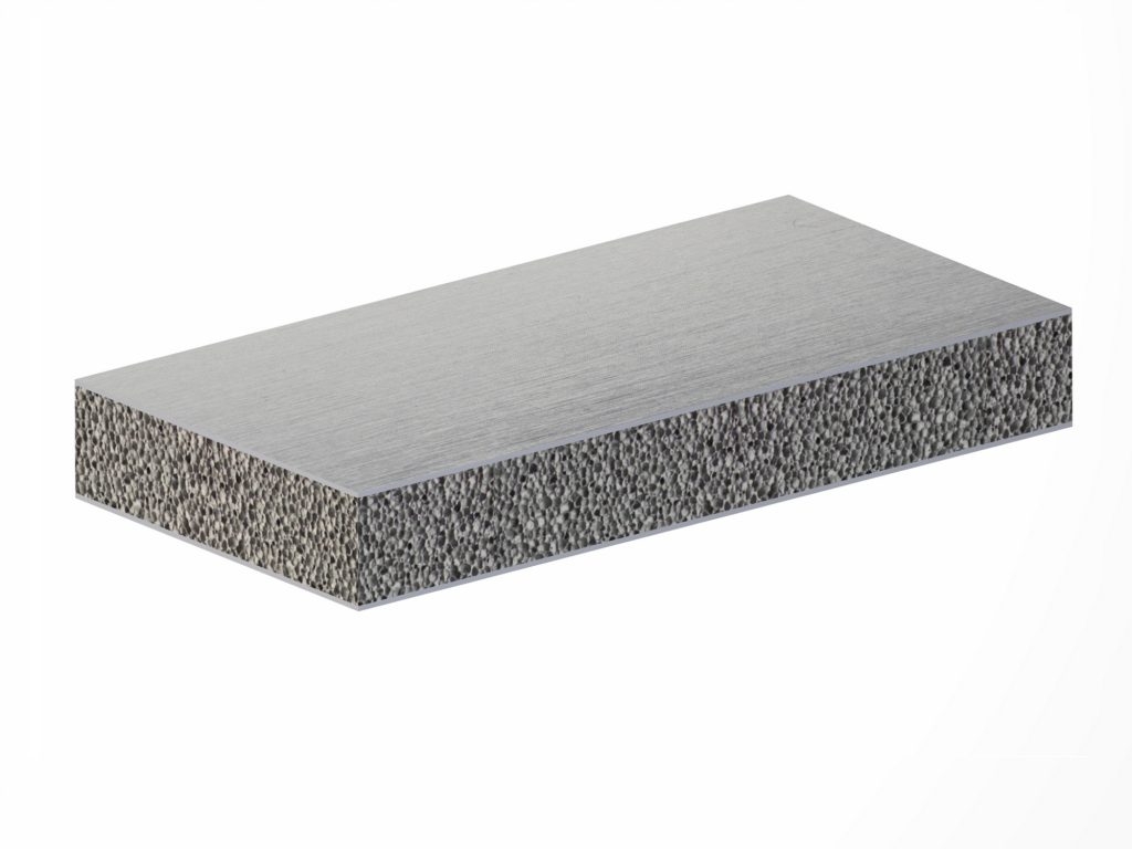
The SM-920 is primarily a metal aircraft featuring semi-monocoque foam metal sandwich construction. Benefiting from a variety of advanced alloys as well as metal forming and joining techniques, Stavatti is reinventing how airplanes are built. As a semi-monocoque aircraft, the SM-920 has external foam metal sandwich skins that are supported by an internal structure of frames, bulkhead, spars and ribs made from high performance titanium and aluminum lithium alloys. Employing a minimal number of rivets or screw fasteners, the SM-920 is built from sandwich skins that are welded to titanium bulkheads, frames, spars and ribs using Laser or Friction Stir Welding (FSW) techniques.
Conceptually similar to aluminum honeycomb sandwich, the foam metal sandwich approach substitutes aluminum honeycomb with a low density metal foam in which a foam metal core is sandwiched between two metal sheets. The foamed metal core will be either titanium foam or aluminum-lithium foam, with face sheets being either aluminum-lithium or titanium. The foam itself will be of either open and closed cell type, depending upon component purpose and application. Offering significant improvements over tradtional semi-monocoque stressed skin aircraft construction, the foam metal sandwich approach builds upon the known advantages of Honeycomb Sandwich structures by adding omni-directional strength as well as substantial tolerance to ballistic impacts. The SM-920’s use of foam metal structures results in airframe structures that are inherently stronger, stiffer, lighter and more affordable to produce.
The closed cell metal foam sandwich structure has an excellent stiffness-to-weight ratio, a greater strength-to-weight ratio than traditional structures and lower thermal conductivity with a high degree of fire resistance. The sandwich construction results in a structure that offers high degree of sound and vibration dampening as well as high impact resistance, fatigue cycle tolerance and superior survivability. Moreover, the closed cell foam structure is conducive to a smooth, low-drag skin-surface that can be produced quickly at a low cost and lower parts count. A new material manufactured by proven and qualified by companies including Fraunhaufer IWU of Chemnitz, Germany, today there are many qualified manufacturers that are producing foam metal sandwich structures for aerospace, defense, automotive, and other applications. Stavatti will be building upon these successes to standardize and qualify a proprietary approach toward the production of foam metal sandwich structures for FAA certified aircraft.
The foam metal sandwich structure will feature skins which are 0.050 to 0.25 in thick separated by a low density foamed metal core measuring as thin as 0.5 to 1.0 in to thicknesses over 12 in for full depth wing structures. The foamed metal core is metallurgically bonded to the metal face sheets on a molecular level. This metallurgical bonding is the result of the in-situ bonded proprietary manufacturing approach whereby the core is foamed between solid face sheets, allowing the foam to fuse and form a molecular bond. The face sheets will use 100% density material while the lower density foam core will have a range of material density from 3% to 10% with an average density of 8%, depending on structural requirements. This foam metal sandwich technology has been utilized by the aerospace industry for over two decades for various applications. Stavatti perceives this technology as a break-through that not only increases aircraft structural integrity but allows significant reductions in airframe fabrication time and cost. Dramatically reducing the cost of titanium components this technology will enable the production of all metal aircraft which significantly eclipse any benefit from the use of fiber composites or other materials, particularly from the standpoint of ballistic survivability, fatigue strength improvement and stiffness.
Having briefed both the Air Force Research Laboratories (AFRL), NAVAIR and DARPA on the foam metal sandwich technology, Stavatti will qualify both aluminum-lithium and titanium foam metal sandwich structures for military and civil aircraft applications through these organizations as part of the comprehensive SM-920 FAA certification and DoD/Military qualification process.
The SM-920 structure is designed for a service life of 60,000 cycles/120,000 hours at an annual usage of 4,000 flight hours for a total lifetime of over 30 years. Aircraft design philosophy has emphasized application of Fail-safe design principles with load-path redundancy. Materials used throughout the aircraft exhibit plastic failure modes and maximum resistance to corrosion in all environmental conditions. The aircraft has been designed to a positive limit load factor of +2.5 g and an ultimate limit load factor of +3.75 g at a Maximum Takeoff Weight (MTOW) of 190,000 lbs. The positive limit load factor at Typical Takeoff Weight is is +2.5 g. For all gross weights, the aircraft’s ultimate load factor is 1.5 times limit load factors.
Fuselage
The SM-920 fuselage is a modular, three section structure composed of a nose, center fuselage and aft fuselage. Total fuselage length is 143 ft. All three fuselage modules feature a semi-monocoque foam metal sandwich structure consisting of aluminum-lithium sandwich skins and a core of low density aluminum foam. Bulkheads, frames and longerons are employed when necessary to enhance the integrity of the foam metal sandwich structure. Skins are smooth for reduced skin friction drag. The fuselage benefits from laser and friction stir welding with mechanical fasteners used primarily in the attachment of removable access hatches and inspection panels. The fuselage is equipped with six plug type cabin doors with three doors located on either side of the aircraft. The fuselage also has two over-the-wing emergency exits with one exit located on either side of the aircraft. The standard fuselage has a total of 45 ovoid passenger windows per side that measure 18 in high and 12 in wide for a total of 90 windows. Fuselage modules are designed to enable the center fuselage section to be stretched for increased aircraft passenger and payload capacity.
The nose module is 35 ft long and is of gracefully sweeping cockpit blended design to reduce transonic drag. The nose houses the aircraft cockpit, flight attendant station with forward galley and closet, two forward lavatories, forward port and starboard cabin plug type doors and up to three rows of economy class seats or equivalent. The nose also houses the aircraft radome which hinges to the port for radar/avionics access. The nose has a three piece birdstrike resistant large area windshield. The nose contains the aircraft nose landing gear and gear bay, primary radar and sensor bay and primary avionics bay. The nose is insulated, pressurized, heated and air conditioned to ensure optimal climatic conditions. The center fuselage has a standard length of 63 ft and is of semi-elliptical cross section measuring 172 in tall and 165 in wide. The center fuselage features an upper passenger deck and a lower cargo and baggage deck. The center fuselage also serves as the structural interface for the aircraft’s wing assembly and the dorsal fin of the vertical stabilizer. The passenger deck offers a maximum interior ceiling height of 90 in and a maximum interior width of 160 in. The minimum interior floor to overhead baggage bin height is 59.5 in.
The fuselage interior is designed to provide a 30 in wide center aisle in a standard six abreast economy class seating arrangement with two three seat units separated by a single aisle. The center fuselage can accommodate up to 24 rows of economy class seats or equivalent. The lower cargo and baggage deck offers a maximum interior height of 48 in and a center floor width of 67 in. The cargo and baggage deck is designed to accommodate standard LD3-45 containers. The center fuselage has two plug type cabin doors and two over-the-wing emergency exits located on the port and starboard fuselage.
The aft fuselage is 45 ft long and accommodates up to five rows of economy class seats or equivalent. The aft fuselage has a large floor area galley for hot food cooking and preparation, flight attendant closets and two industry leading large footprint lavatories. The aft fuselage has two plug type cabin doors located on the port and starboard fuselage behind the last passenger seating row. The aft fuselage serves as the structural interface for the aircraft’s horizontal and vertical stabilizers. The aft fuselage also houses the aircraft’s Auxiliary Power Unit (APU) which exhausts through the aft fuselage tailcone. The aft fuselage is of gracefully tapered design that concludes with a distinctive boat-tail to reduce drag.
Wings
The wings of the SM-920 are of high aspect ratio, lower to mid fuselage, cantilever design. To reduce transonic drag the wings are of novel M planform configuration with curved leading and trailing edges with a distinctly curved swept wingtip. The M wing is unique to the SM-920 design and enables the aircraft to have a high speed cruise while efficiently achieving high lift coefficients for low takeoff and landing speeds. Consisting of a forward swept inboard wing and aft swept outboard wing sections, the inboard wing has a mean forward sweep of 54.5° at the 25% chord with a dihedral of 4°. The outboard wing has a mean sweepback of 40.3° at the 25% chord with an anhedral of 5°. Aircraft overall wingspan is 124 ft with a reference wing area of 1,500 sq ft. Wing aspect ratio is 10.25 while the wing airfoil is a proprietary supercritical section of 10% thickness. Wings are equipped with an Electro-Expulsive Separation System (EESS) for in-flight deicing.
Wings are equipped with outboard ailerons for roll control, trailing edge triple slotted Fowler flaps, leading edge slats and spoilers for directed lift and to serve as spoilers/speedbrakes. Ailerons are equipped with electric trim tabs and include single port and starboard units. Slats are split into five distinct, independently deployable sections per wing and may be deployed differentially allowing ailerons to receive accelerated flow to prolong the onset of tip stall. Slats include two inboard and three outboard slats per wing for a total of ten slats on the aircraft. The triple slotted Fowler flaps consist of four flap assemblies per wing including two inboard flaps and two outboard flaps for a total of eight aircraft wing flap assemblies. The flaps may be deployed to a maximum of 50°. Each wing has a total of four spoiler/speedbrakes including two inboard and two outboard spoilers. The spoilers may be operated differentially to provide roll control, to serve as lift dumpers and for gust alleviation. Ailerons, flaps, slats, spoilers and speed-brakes are of aluminum foam metal sandwich construction and are controlled using a digital, full authority power-by-wire flight control system with electromechanical actuators.
The wing is of foam metal sandwich type composed of aluminum-lithium and titanium skins, titanium and aluminum-lithium spars and ribs, aluminum-lithium foam metal cores and full-depth titanium foam metal fuel cell cores. Wing spars feature sine-wave webs and form a rigid carry-through box. The wing is constructed using laser and robotic forming and features both laser and friction stir welding throughout. Mechanical fasteners used primarily in the attachment of removable access hatches and inspection panels. Each wing is mounted to the aircraft fuselage by spar attachment fittings that bolt to fuselage bulkheads. Wings are built in four pieces including the inboard and outboard sections which are mechanically joined. The wing configuration and structure is designed to accommodate the aircraft engine nacelles which blend into the trailing edge of the wing at the inboard and outboard wing joint.
Wing fuel cell cores are porous, open cell titanium foam metal cores that serve as fuel tanks. The foam metal fuel tanks aid in reducing the chance of fuel ignition or explosion and allow for pressurization with inert gas. Wing foam core fuel tanks have a total capacity of 3,462 USG per wing. Each wing features milled aluminum-lithium and titanium skins that are laser welded to the spar and rib substructure and molecularly bonded to the foam core. A foam metal sandwich structure, SM-920 wings are stronger, stiffer and lighter than conventional semi-monocoque wings.
Horizontal Stabilizer
The SM-920 features a horizontal stabilizer for longitudinal pitch stability. Of cantilever design, the root of the horizontal tail is mounted to the aft fuselage while the tip is mounted to the aircraft engine nacelles. The horizontal tail is of forward swept, untapered, semi-cresent planform with a mean leading edge sweep of -34.6° and trailing edge sweep of -34.6°. Horizontal tail unit span is 22.75 ft for an overall combined span of 45.5 ft. Horizontal tail unit area is 35.75 sq ft. Total horizontal tail area is 544.7 sq ft with an aspect ratio of 1.33. Horizontal tail mean airfoil is a propriety symmetrical section of 9% thickness. The horizontal tail is equipped with elevators totalling 149 sq ft in area. Elevators are electromechanically actuated. The elevators can be deflected collectively for pitch control or differentially for role control with a maximum deflection angle of +/- 40°. The horizontal tail features aluminum-lithium foam metal sandwich construction featuring three titanium primary spars, titanium ribs and a foam metal sandwich structure including aluminum-lithium skins molecularly bonded to in-situ formed full-depth aluminum lithium foam metal cores. Elevators are of foam metal sandwich construction with a full depth core. The horizontal tail is equipped with an Electro-Expulsive Separation System (EESS) for in-flight deicing.
Vertical Stabilizer
The SM-920 has a single vertical stabilizer of trapezoidal planform with dorsal fairings and a swept tip. The vertical tail is positioned relative to the horizontal tail to enable the aircraft to rapidly recover from any departure associated with high AoA, stalls and spins. Vertical tail leading edge sweep is 50°and trailing edge sweep is 25°. With an overall span of 23 ft 7 in, the vertical tail has 412 sq ft of area including the dorsal fin. The vertical tail reference area is 386.7 sq ft with a corresponding aspect ratio of 1.34. With a dihedral angle of 90°, the vertical tail’s mean airfoil is a propriety symmetrical section of 9% thickness. The vertical tail has a rudder for yaw control. Rudder area is 90.4 sq ft. The rudder has a trim tab and is capable of deflection angles of +/- 35°. The vertical tail features aluminum-lithium foam metal sandwich construction featuring three titanium primary spars, titanium ribs and a foam metal sandwich structure including aluminum-lithium skins molecularly bonded to in-situ formed full-depth aluminum lithium foam metal cores. The tip of the vertical tail has an aramid composite antenna fairing for vertical tail mounted antennas. The rudder is of foam metal sandwich construction with a full depth core. The rudder is actuated by an electromechanical actuator with integral yaw dampener. The vertical tail is equipped with an Electro-Expulsive Separation System (EESS) for in-flight deicing.
Nacelles
The SM-920 has twin engine nacelles each housing a single powerplant. The nacelles are positioned symmetrically 312 inches from the aircraft centerline. Measuring 60 ft long at their centerline, each nacelle contains the aircraft powerplant as well as a single main landing gear unit that retracts upward into the nacelle. The nacelles attach to the wing at the forward and aft sweep junction of the M wing, the nacelle intake face is located below the wing to enable favorable airflow at high AoA. The tip of the aircraft’s horizontal stabilizer attaches to the aft inboard structure of the nacelle.
The nacelle serves as a structural element connecting the wing to the horizontal stabilizer resulting in a rigid load-sharing box consisting of the fuselage, wing, horizontal tail and nacelle. Designed for mass flows of up to 965 lbs/sec, the nacelle incorporates a pitot inlet with a forward swept bottom lip and serpentine duct to improve pressure recovery at Mach numbers in excess of 0.85. The nacelle is designed to accommodate the P&W PW1133G-JM and the CFM International LEAP-1A32 powerplant or a variety of other powerplants, including the Stavatti/NeoThrust E750-AFT-360. The powerplant is fitted with a noise dampening exhaust duct which when combined with proprietary intake and exhaust duct acoustical liners is anticipated to result in significantly lower noise levels than competitor aircraft. The exhaust duct blends into a 2-D thrust vectoring nozzle that offers both variable geometry and thrust reversing. The 2-D nozzles may be used in conjunction to enhance pitch control or diferentially to enhance both pitch and roll control. Use of thrust vectoring can reduce aircraft takeoff distance, improve maneuvering, reduce transonic roll-coupling, as well as assist in reducing trim drag by serving as an alternative mechanism to provide pitch trim.
Aircraft Systems
SM-920 Aircraft Systems include flight controls, electromechanical systems, electrohydrostatic systems, hydraulic systems, electrical system, cabin air conditioning, heating and pressurization system and APU.
The SM-920 flight control system is a full-authority, digital Power-By-Wire (PBW) flight control system. The PBW system features self-contained electrohydrostatic primary flight control actuators (EHAs), electromechanical actuators (EMAs) and electrically driven power drive units (PDUs). EHAs and EMAs are developed and produced by leading industry team members including Moog, Parker Aerospace and Beaver Aerospace. EHAs and EMAs position and actuate the aircraft’s ailerons, flaps, flapperons, slats, spoilers, rudders, stabilators, air stair, landing gear, landing gear doors and speedbrake.
The SM-920 EHAs enable flight control and systems actuation without the need for a central hydraulic system resulting in reduced aircraft weight, more efficient power consumption and improved aircraft maintainability. The EHAs consist of an integral fixed displacement reversible high speed pumps driven by a brushless electric motors. The EHAs are dual tandem designs with simplex hydraulic output that incorporate both fail-safe features and overload protection. The EHAs have operating pressures up to 5,000 psi with an electrical output range of 270 Vdc or 115 VAC with a transformer rectifier.
The SM-920 EMAs include both linear and rotary electromechanical actuators that utilize a ball or Acme screw driven by brushless electric motors through a torque sum gear train. The EMAs my have a skewed roller or a fail-safe electromechanical brake. Linear or rotary variable differential transformers determine position of flight control surfaces actuated by the EMA. In the event of primary load path failure, the EMA’s primary load path is locked in place and load is transferred to a secondary load path. The PBW system is triplex, features BIT and benefits from flight control laws that enable variable stability and provide the pilot with maximum flight control authority enabling the aircraft to maneuver thorughout the air transport flight category envelope. PBW flight control law software allows the aircraft to perform all standard maneuvers including the stall, slip and spin. The PBW architecture interfaces directly with pilotless remote piloted and autonomous flight command systems. Ailerons, flaperons, rudders and elevators are internally mass balanced. Flight control surfaces may be deflected in concert or independently to enable unique flight control deflections and resulting aircraft maneuvers as controlled by the aircraft flight control system.
Flight crews may pre-program specific maneuvers for precision execution by the aircraft flight control system.
The SM-920 features two independent 4,000 psi (276 bar) hydraulic systems driven by electrically driven pump. Hydraulic systems are interconnected. Hydraulic systems actuate landing gear normal braking and nose wheel steering. Hydraulic pressure is maintained automatically and is suitable for inverted flight.
The SM-920 electrical system supplies 115/200 volt, three-phase, 400 cycle AC power and 28 VDC per MIL-STD-704D. The electrical system is powered by two engine driven Hamilton Sunstrand 90 kVA constant frequency generators as well a third APU driven 90 kVA generator. Four independent sources are used for power generation including two engine driven generators, an APU driven generator and a battery. AC power is supplied by two static inverters. Power is normally supplied by one inverter with the second serving as a backup. DC power is supplied by one 24 VDC battery. The starter/generator is a combination engine starter and 28 VDC generator. The secondary generator is a 28 VDC generator. An external 28 VDC ground power connector is provided. The SM-920 features a Honeywell 131-9B series Auxiliary Power Unit (APU) for ground power and emergency in-flight power. With a start-up ceiling of 41,000 ft and a 410 lb dry weight the 131-9B APU provides 90 kVA. The APU is mounted in the aft fuselage tail cone. The 131-9B may be replaced by a new design, high efficiency NeoThrust Axial Piston APU developed by Suter Industries when available.
The Aircraft is equipped with a Phyre Technologies GOBIGGS Green On-Board Inert Gas Generation System for fuel tank explosive protection. The aircraft cockpit and cabin is pressurized, air conditioned and heated. The aircraft will feature an Electro-Expulsive De-icing System (EEDS) as developed by NASA and produced by IMS-ESS. EEDS is used for wing leading edge, horizontal stabilizer leading edge and vertical stabilizer leading edge and air intake deicing. Electric deicing is used in the pitot tube, static ports, AoA transmitter, stall warning sensor and air data computer sensors. Hot air deicing is provided for the aircraft windshield. A fire detection and suppression system is provided for the engine, avionics bay, cargo bays, cockpit and cabin.
Fuel System
The aircraft fuel system is composed of eight wing fuel tanks and two nacelle mounted engine feeder tanks. The wing fuel tanks consist of three tanks located within the port and starboard wing respectively and two center section tanks. The wing fuel tanks are of foam metal sandwich design consisting of a porous titanium foam metal core. For increased survivability the fuel tanks are pressurized with a Phyre Technologies GOBIGGS. The aircraft design internal fuel load is 45,000 lbs equivalent to 6,717 USG of JP-8 or 6,924 USG of JP-4 at standard conditions. SM-920 fuel tanks are sized for a maximum capacity of 6,925 usable gallons of JP-4 plus additional volume necessary for volume necessary for fuel tank features. Engine fuel manifolds are connected by use of crossfeed valves. Each fuel tank uses two electric fuel pumps that are cooled and lubricated by fuel passing through the pump. A single point pressure refueling interface is provided in a ground refueling panel on the bottom of the right wing. The single point refueling interface enables rapid refueling and defueling as well as the ground transfer of fuel between tanks. Maximum fueling rate is 300 USG/Min at 50 psi. The aircraft may be equipped with a flying-boom style Universal Aerial Refueling Receptacle Slipaway Installation (UARRSI) mounted on the centerline dorsal fuselage aft of the cockpit to enable the in-flight refueling of SM-920 military variants.
Landing Gear
The SM-920 has electromechanically actuated, retractable conventional tricycle landing gear. The landing gear features a long, shock-strut stroke to ensure that a 1.5g landing load factor is not exceeded. The aircraft design rate-of-sink at a normal design gross weight of 185,000 lbs is 10 ft/sec. The entire airplane is designed for a 2.0g taxi and dynamic taxi load at all weights and fuel distributions up to a maximum takeoff weight of 190,000 lbs. Landing gear struts are of SP 700 Titanium and Ferrium S53 construction. SM-920 wheelbase is 68 ft 4 in. SM-920 wheel track is 52 ft 0 in.
The nose landing gear retracts forward and is an oelo-pneumatic, dual wheeled unit. The nose wheel uses 27 x 8.75-14.5 size tires including 24 ply, Goodyear Flight Leader tires with a maximum inflation pressure of 160 psi. Wheels are free rotating and the gear is retracted by an electromechanical actuator which extends to retract the gear forward and upward. In the event of actuator failure, the nose gear drops and is locked in the extended position. Nose wheel steering is hydraulically actuated and is provided via rudder pedal inputs. The nose strut features a taxi light that steers with the nose wheel.
The main landing gear consists of two nacelle mounted, single-strut, oelo-pneumatic, two wheel units featuring hydraulic carbon disk brakes. The main wheels use 44.5 x 16.5-21 size tires including 28 ply Goodyear Flight Leader tires with a maximum inflation pressure of 214 psi. The main gear retracts forward and up into the engine nacelles where they are fully enclosed. Main gear struts are machined titanium structures. Main gear actuation is from a self-locking electromechanical actuator. Each main gear unit is mounted on a trunnion and features a universal drag link and drag struts. Main landing ger feature an oleo strut for shock absorption. The landing gear features a manually driven emergency lowering system.
An actuator dampens wheel oscillation and positions the wheels during landing and retraction. The main gear is attached to a ventral landing gear bay within each engine nacelle, one main gear unit per nacelle. A self-locking electromechanical actuator extends to retract the gear forward and upward into the main gear bay. In the event of actuator failure, the gear extends assisted by gravity free fall and locks in the extended position.
Two hinged doors, including one inboard and one outboard, enclose the main gear bays with a series of links, rods and levers used to mechanically sequence the gear doors with the landing gear. Main gear brakes are equipped with hydraulic lock-out valves to prevent progressive failure of all eight brakes. Main gear breaks also incorporate anti-skid features. In the event of brake hydraulic system failure an accumulator will provide five full brake applications. Each main gear strut may feature a single landing and taxi light.
Certification & Qualification
The SM-920 will be Type Certified as a Transport Category aircraft under Federal Aviation Administration (FAA) Federal Aviation Regulations (FAR) Part 25-Airworthiness Standards for Transport Category Airplanes (14 CFR Part 25). The certification basis for the aircraft will be Title 14, Code of Federal Regulations (14 CFR) part 25 as amended by Amendments 25-0 through 25-137, plus Amendment 25-141 with exceptions permitted by 14 CFR 21.101. This comprehensive regulation governs all aspects of a commercial passenger airliner’s design, including flight performance, structures, design and construction, powerplant installation, systems and equipment, and operating limitations. Compliance with Part 25 ensures the aircraft meets the highest levels of safety, reliability, and performance required for commercial passenger operations under Parts 121 or 135. The SM-920 will be equipped and FAA-certified for commercial day and night IFR operations, including the required instrumentation, avionics, and systems redundancy mandated under Part 25 Subparts B (Flight), D (Design and Construction), F (Equipment), and G (Operating Limitations). This certification will encompass full compliance with performance, controllability, systems safety, lightning protection, fire protection, and human factors requirements, enabling safe, reliable, and efficient operations worldwide under the most demanding commercial airline conditions. By meeting or exceeding these rigorous FAA Part 25 standards, the SM-920 will deliver industry-leading safety, operational flexibility, and economic performance throughout its long service life. The airplane is designed to be free from flutter, buzz, divergence and all other related aeroelastic instabilities up to 1.2 Vdive. The Aircraft is also designed to meet 14 CFR Part 34 fuel venting and exhaust emission requirements for turbine engine powered airplanes and 14 CFR Part 36 Noise Standards. The aircraft will be certified to operated with a minimum crew of two (pilot and copilot) and a maximum number of passengers of 192 seats in the standard configuration and up to 222 passengers in the stretched configuration with a fuselage plug. The SM-920 will receive a Production Certificate and will be flight tested and qualified at a civil commercial flight test center including, but not limited to the flight test center facilities available at the Southern California Logistics Airport.
Operational Costs
The SM-920 will have an operational Cost Per Flight Hour (CPFH) of approximately $7,480 per hour, including an aircrew cost of $1,200 per hour and a fuel cost of $3,029 per hour. The CPFH estimates assume an annual utilization rate of 4,500 flight hours. The SM-920 has been designed for a baseline operational service life of 120,000 hours, accumulating an average of 4,500 hours per annum. Aircraft fatigue life will be based upon 60,000 pressurization cycles. The aircraft maximum design load factor limit is +2.5-g at Maximum Gross Takeoff Weight (MTOW) with maximum payload and full internal fuel. The SM-920 is designed for operation in arid, desert, tropical, arctic and sea-salt environments and is capable of functioning without reduction in mission capable rates in -25°C to 55°C environments. The SM-920 will be able to operate in ground conditions from -25°C to 55°C and in flight conditions from -55°C to 60°C.
Performance & Specifications
MODEL
SM-920
TYPE
Next Generation Twin Engine Single Aisle Narrowbody Commercial Airliner
FLIGHT CREW
Flight Crew of Two and Three to Six Flight Attendants
PASSENGER CONFIGURATIONS
204 Passengers in an All-Economy Class Arrangement with 32 in Seat Pitch
187 Passengers in a Business/Economy Two Class Arrangement (20/156 Passengers)
180 Passengers in a First/Economy Two Class Arrangement (12/156 Passengers)
162 Passengers in a Premium-Economy Class Arrangement with 38 in Seat Pitch
POWERPLANT
Two (2) PW 1133G-JM Geared Turbofans Delivering 33,110 lbs st; Total Aircraft sl st of 66,220 lbs. The powerplant is fitted with variable geometry, thrust vectoring and reversing 2D nozzle.
STRUCTURE
Semi-monocoque aluminum lithium foam metal sandwich construction throughout with three titanium sine-wave spars in the cantilever wings and empennage. Titanium metal ceramics (cermets) used in high temperature regions.
| DIMENSIONS | WEIGHTS & CAPACITIES | ||
|---|---|---|---|
| Wingspan | 124 ft 0 in | Empty Weight | 100,000 lbs |
| Length Overall | 150 ft 0 in | Maximum Internal Fuel | 45,000 lbs |
| Height Overall | 43 ft 4 in | Max Fuel Payload | 43,000 lbs |
| Wing Area | 1,500 sq ft | Max Useful Load | 90,000 lbs |
| Wing Aspect Ratio | 10.25 | Typical Takeoff Weight (TTW) | 190,000 lbs |
| Wing LE Sweep | 36 degrees | Max Take-Off Weight (MTOW) | 190,000 lbs |
| ESTIMATED PERFORMANCE | ESTIMATED PERFORMANCE | ||
|---|---|---|---|
| Max Level Speed @ SL | 0.95 Mach | Max Initial Rate-of Climb @ SL-MTOW | 10,110 ft/min |
| Max Level Speed @ 35,000 ft | 0.95 Mach | Service Ceiling Exceeds | 45,000 ft |
| Max Cruise Speed @ SL | 0.90 Mach | Range @ 0.85 Mach/35,000 ft | 3,640 nm |
| Max Cruise Speed @ 35,000 ft | 0.90 Mach | Range @ 0.85 Mach/40,000 ft | 3,684 nm |
| Typical Cruise Speed @ SL | 0.85 Mach | Range @ 0.90 Mach/35,000 ft | 3,345 nm |
| Typical Cruise Speed @ 30,000 ft | 0.85 Mach | Range @ 0.90 Mach/40,000 ft | 3,516 nm |
| Typical Cruise Speed @ 35,000 ft | 0.85 Mach | Range @ 0.95 Mach/43,000 ft | 3,003 nm |
| Typical Cruise Speed @ 40,000 ft | 0.85 Mach | Takeoff-Ground Roll, Takeoff Weight | 4,765 ft |
| Typical Takeoff Speed-MTOW @ SL | 157 KTAS | Takeoff over 50 ft, Takeoff Weight | 5,853 ft |
| Typical Approach Speed-TLW @ SL | 122 KTAS | Landing-Ground Roll, Landing Weight | 1,324 ft |
| Stall Speed-TLW @ SL | 106 KTAS | Landing over 50 ft, Landing Weight | 2,208 ft |
Performance & Specifications
MODEL
SM-920
TYPE
Next Generation Twin Engine Single Aisle Narrowbody Commercial Airliner
FLIGHT CREW
Flight Crew of Two and Three to Six Flight Attendants
PASSENGER CONFIGURATIONS
204 Passengers in an All-Economy Class Arrangement with 32 in Seat Pitch
187 Passengers in a Business/Economy Two Class Arrangement (20/156 Passengers)
180 Passengers in a First/Economy Two Class Arrangement (12/156 Passengers)
162 Passengers in a Premium-Economy Class Arrangement with 38 in Seat Pitch
POWERPLANT
Two (2) CFM LEAP 1A32 Turbofans Delivering 32,900 lbs st; Total Aircraft sl st of 65,800 lbs. The powerplant is fitted with variable geometry, thrust vectoring and reversing 2D nozzle.
STRUCTURE
Semi-monocoque aluminum lithium foam metal sandwich construction throughout with three titanium sine-wave spars in the cantilever wings and empennage. Titanium metal ceramics (cermets) used in high temperature regions.
| DIMENSIONS | WEIGHTS & CAPACITIES | ||
|---|---|---|---|
| Wingspan | 124 ft 0 in | Empty Weight | 100,500 lbs |
| Length Overall | 150 ft 0 in | Maximum Internal Fuel | 45,000 lbs |
| Height Overall | 43 ft 4 in | Max Fuel Payload | 42,500 lbs |
| Wing Area | 1,500 sq ft | Max Useful Load | 89,500 lbs |
| Wing Aspect Ratio | 10.25 | Typical Takeoff Weight (TTW) | 190,000 lbs |
| Wing LE Sweep | 36 degrees | Max Take-Off Weight (MTOW) | 190,000 lbs |
| ESTIMATED PERFORMANCE | ESTIMATED PERFORMANCE | ||
|---|---|---|---|
| Max Level Speed @ SL | 0.95 Mach | Max Initial Rate-of Climb @ SL-MTOW | 10,019 ft/min |
| Max Level Speed @ 35,000 ft | 0.95 Mach | Service Ceiling Exceeds | 45,000 ft |
| Max Cruise Speed @ SL | 0.90 Mach | Range @ 0.85 Mach/35,000 ft | 3,552 nm |
| Max Cruise Speed @ 35,000 ft | 0.90 Mach | Range @ 0.85 Mach/40,000 ft | 3,545 nm |
| Typical Cruise Speed @ SL | 0.85 Mach | Range @ 0.90 Mach/35,000 ft | 3,262 nm |
| Typical Cruise Speed @ 30,000 ft | 0.85 Mach | Range @ 0.90 Mach/40,000 ft | 3,389 nm |
| Typical Cruise Speed @ 35,000 ft | 0.85 Mach | Range @ 0.95 Mach/43,000 ft | 2,985 nm |
| Typical Cruise Speed @ 40,000 ft | 0.85 Mach | Takeoff-Ground Roll, Takeoff Weight | 4,431 ft |
| Typical Takeoff Speed-MTOW @ SL | 157 KTAS | Takeoff over 50 ft, Takeoff Weight | 5,520 ft |
| Typical Approach Speed-TLW @ SL | 122 KTAS | Landing-Ground Roll, Landing Weight | 1,325 ft |
| Stall Speed-TLW @ SL | 106 KTAS | Landing over 50 ft, Landing Weight | 2,208 ft |
Performance & Specifications
MODEL
SM-920
TYPE
Next Generation Twin Engine Single Aisle Narrowbody Commercial Airliner
FLIGHT CREW
Flight Crew of Two and Three to Six Flight Attendants
PASSENGER CONFIGURATIONS
204 Passengers in an All-Economy Class Arrangement with 32 in Seat Pitch
187 Passengers in a Business/Economy Two Class Arrangement (20/156 Passengers)
180 Passengers in a First/Economy Two Class Arrangement (12/156 Passengers)
162 Passengers in a Premium-Economy Class Arrangement with 38 in Seat Pitch
POWERPLANT
Two (2) NeoThrust E750-AFT-360 Turbofans Delivering 36,000 lbs st; Total Aircraft sl st of 72,000 lbs. The powerplant is fitted with variable geometry, thrust vectoring and reversing 2D nozzle.
STRUCTURE
Semi-monocoque aluminum lithium foam metal sandwich construction throughout with three titanium sine-wave spars in the cantilever wings and empennage. Titanium metal ceramics (cermets) used in high temperature regions.
| DIMENSIONS | WEIGHTS & CAPACITIES | ||
|---|---|---|---|
| Wingspan | 124 ft 0 in | Empty Weight | 97,000 lbs |
| Length Overall | 150 ft 0 in | Maximum Internal Fuel | 48,000 lbs |
| Height Overall | 43 ft 4 in | Max Fuel Payload | 43,000 lbs |
| Wing Area | 1,500 sq ft | Max Useful Load | 93,000 lbs |
| Wing Aspect Ratio | 10.25 | Typical Takeoff Weight (TTW) | 190,000 lbs |
| Wing LE Sweep | 36 degrees | Max Take-Off Weight (MTOW) | 190,000 lbs |
| ESTIMATED PERFORMANCE | ESTIMATED PERFORMANCE | ||
|---|---|---|---|
| Max Level Speed @ SL | 0.95 Mach | Max Initial Rate-of Climb @ SL-MTOW | 11,233 ft/min |
| Max Level Speed @ 35,000 ft | 0.95 Mach | Service Ceiling Exceeds | 45,000 ft |
| Max Cruise Speed @ SL | 0.90 Mach | Range @ 0.85 Mach/35,000 ft | 4,137 nm |
| Max Cruise Speed @ 35,000 ft | 0.90 Mach | Range @ 0.87 Mach/35,000 ft | 4,083 nm |
| Typical Cruise Speed @ SL | 0.85 Mach | Range @ 0.90 Mach/35,000 ft | 3,329 nm |
| Typical Cruise Speed @ 30,000 ft | 0.85 Mach | Range @ 0.90 Mach/45,000 ft | 3,613 nm |
| Typical Cruise Speed @ 35,000 ft | 0.85 Mach | Range @ 0.95 Mach/40,000 ft | 2,784 nm |
| Typical Cruise Speed @ 40,000 ft | 0.85 Mach | Takeoff-Ground Roll, Takeoff Weight | 4,291 ft |
| Typical Takeoff Speed-MTOW @ SL | 157 KTAS | Takeoff over 50 ft, Takeoff Weight | 5,379 ft |
| Typical Approach Speed-TLW @ SL | 121 KTAS | Landing-Ground Roll, Landing Weight | 1,319 ft |
| Stall Speed-TLW @ SL | 105 KTAS | Landing over 50 ft, Landing Weight | 2,198 ft |
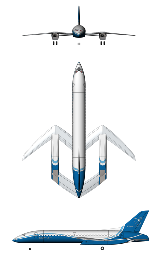
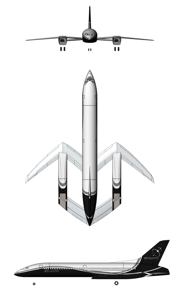
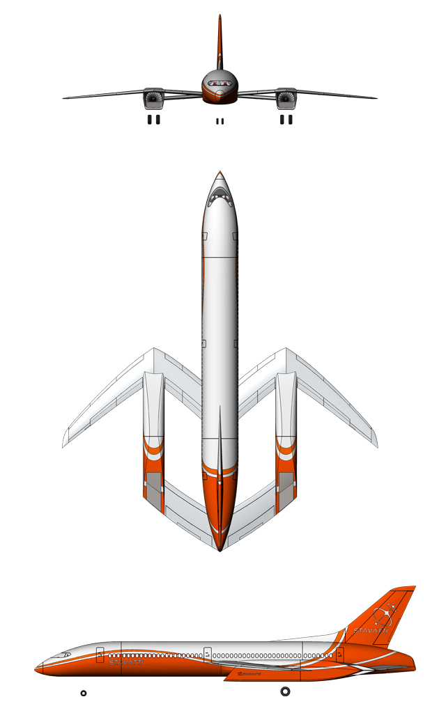
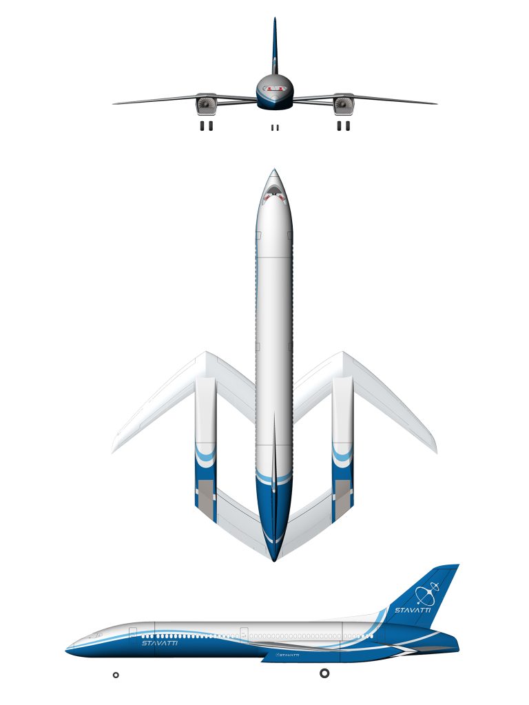
SM-920 Airliner General Arrangement
Cost
The SM-920 Commercial Airliner is now under development and is not currently in production. Qualified customers are invited to place Pre-Orders or issue a Letter of Intent for SM-920 aircraft at this time. Upon entering production, the Per Unit Flyaway Cost (Flyaway Cost) of SM-920 aircraft will be dependent upon the specific model, model block configuration, customer selected powerplant, sensor-avionics-instrumentation-electronic warfare-armament systems package, and all related support equipment specific to an individual aircraft, not including spares, Stavatti provided maintenance or ground support equipment.
Based upon a Standard Aircraft Configuration (SAC) developed for each member of the SM-920 family in support of the marketing and export of aircraft to commercial airlines worldwide, a Rough Order of Magnitude (ROM) Per Unit Basic Flyaway Cost has been projected. Projected ROM Flyaway Costs for Initial Production SM-920 aircraft of Basic SAC are as provided. All projected ROM costs herein provided are approximate estimations issued to assist potential commercial airlines for future fleet budget planning only. Projected ROM costs are not contractually binding. The current year Basic Aircraft Flyaway Cost is:
$100,000,000
The Basic Per Unit Flyaway Cost of SM-920 aircraft will be approximately $100,000,000 (one hundred million) United States Dollars (USD), depending upon specific model and configuration.
These ROM, approximate Flyaway Costs apply to one (1) SM-920 Commercial Aircraft of Standard Aircraft Configuration (SAC). In an effort to simplify the marketing and distribution of the SM-920 Commercial Airliner worldwide, Stavatti has developed the SAC. The SM-920 SAC represents a common SM-920 configuration which is readily suitable for mass production and expedient delivery to the customer. Stavatti customers will be able to purchase SM-920 SAC aircraft at a specified flyaway cost plus applicable duties and export/delivery expenses.
SM-920 SACs are specified within the SM-920 Configuration Control Statement (CCS) document as issued by Stavatti Aerospace Ltd. for specific SM-920 models as appropriately configured for specific domestic and allied customers. Contact Stavatti or visit SM-920 Product Literature for a copy of an appropriate CCS. A portion of the avionics, displays and related systems associated with the SM-920 SAC are also indicated in the Specifications page of this website. The following support documentation, options, equipment and material is also included with each SM-920 of SAC:
U.S. Standard Airworthiness Certificate, Export Certificate of Airworthiness, Weight and Balance Data Sheets/Weight and Balance Plotter, Aircraft/Engine/Armament System Log Books, Abbreviated Checklist, Flight Manual, Pilot‘s Operating Manual, Avionics Wiring Diagrams, Hydromechanical Systems Manual, Maintenance Manual (Airframe), Illustrated Parts Catalog (Airframe), Wiring Diagram Manual (Airframe), Weight and Balance Manual, Component Maintenance Manual, Structural Repair Manual, System Control Code Programmers Manual, Illustrated Tool and Equipment Manual, Nondestructive Inspection Manual, Engine Maintenance Manuals, Engine Illustrated Parts Catalogs, Parts Warranty Listing, additional miscellaneous information concerning engine, airframe and avionics support, Aircraft mooring system (including moorings, wheel chocks, control locks, pitot-static port covers, etc.), Aircraft Sunshades/Covers, Comprehensive Aircraft Maintenance System Tool Kit, Aircraft Emergency Survival Provisions, Stavatti provided operational ground schooling and orientation for two flight officers, Stavatti provided maintenance and service ground schooling and orientation for a maintenance team of five, Custom Paint Scheme consisting of up to 10 base colors and up to 25 trim colors, Single Full Internal Fuel Load consisting of Jet-A installed in aircraft, additional equipment and a 2,000 Flight-Hour Manufacturer’s Warranty.
All publications, documents and manuals will be provided in both hardcopy bound print as well as Digital format. In addition to documentation supplied by Stavatti Commercial Aerospace, additional documentation may be provided detailing the operation/maintenance of specific aircraft systems by specific aircraft system manufacturers. Stavatti will provide Service Bulletins, Service Letters, Air Worthiness Directorates and manual revisions for the duration of aircraft operational service life.
The Flyaway Cost of the SM-920 does not include the cost of any spares, ground support equipment or other logistical support that may be associated with a commercial aircraft procurement contract. The additional costs associated with the provision of spares, Contractor Logistical Support or any other indicative cost options, maybe provided by Stavatti. All Flyaway Cost data provided herein is not contractually binding and are conceptual in nature.
The noted Flyaway Costs only apply to the SM-920 of SAC. The SM-920 SAC does not represent aircraft configured to satisfy specific customer requirements. Stavatti desires to satisfy all customer needs and requirements. In so doing, the SM-920 will employ open avionics and systems architecture allowing the SM-920 to employ a wide variety of avionics and sensor systems. Customers are invited to procure aircraft which employ customized systems configurations, as specially developed by Stavatti. The Flyaway Cost of SM-920 aircraft of customized configuration will be dependent upon the systems specified and is determined only upon assessment of the specific configuration. Generally, the Flyaway Cost of SM-920 aircraft as projected will fall between $90 million and $120 million dependent upon specific aircraft configuration.
AVAILABILITY
The SM-920 commercial aircraft is currently under development by Stavatti Aerospace Ltd.-Commercial Aerospace Division. The SM-920 is not currently in production and is not available for delivery at this time. Stavatti is receiving and accepting Pre-Orders and Deposits for the purchase of the SM-920 at the present time, hence initial production aircraft will be produced in satisfaction of backlog orders. The estimated time-frames for initiation of Low Rate Initial Production (LRIP), Initial Operational Capability (IOC) within end-user air defense arms and Full Rate Production (FRP) are as projected:
| AIRCRAFT MODEL | PROGRAM PHASE | TIME-FRAME |
|---|---|---|
| SM-920 Airliner |
LRIP: | Contact Stavatti |
| IOC: | Contact Stavatti | |
| FRP: | Contact Stavatti |
Stavatti reserves the right to adjust, modify, expedite, cancel or otherwise enhance the projected dates for SM-920 series LRIP, IOC or FRP at our discretion. All program phase time-frame estimates are for the benefit of future commercial airliner fleet planners and are non-contractually binding.
Prior to entering Full Rate Production (FRP), the SM-920 Commercial Airliner must complete a comprehensive RDT&E program, followed by twenty-four (24) to thirty-six (36) months of Low Rate Initial Production (LRIP). The SM-920 RDT&E program will result in the fabrication of a minimum of six (6) SM-920 Prototype Air Vehicles (PAVs) which will undergo over 6,500 hours of flight testing. Conclusion of the flight test program will result in FAA FAR 25 type and production certification .
LRIP consists of a one to three year gradual ramp-up of production, focused upon the manufacture of fifty (50) to seventy five (75) SM-920 production aircraft. All aircraft produced during LRIP are considered Production Articles. The first one (1) to three (3) SM-920s produced in LRIP will likely remain in possession of Stavatti to serve as company demonstrators. The remaining SM-920s produced during LRIP will be delivered to satisfy customer orders. Due to security restrictions, Stavatti does not openly publish the current backlog for SM-920 orders. Stavatti will begin satisfying this backlog through LRIP.
Full-Rate Production will result in the production of between 500 and 600 SM-920 aircraft annually, with an anticipated SM-920 delivery lead time of 12 months. All SM-920 production availability schedules are subject to change.
PURCHASE
To purchase or order the SM-920 Commercial Airliner please complete and submit the following Letter of Intent (LOI) or Purchase Agreement (PA) forms:
SM-920 aircraft are marketed and sold directly by Stavatti to the end user as a Direct Commercial Sale (DCS) utilizing a Fixed Cost Contract (FCC) structure. The typical purchase process for the Direct Commercial Sale (DCS) of all Stavatti commercial aircraft includes:
1) The purchaser provides Stavatti with a Letter of Intent (LOI). The LOI is a statement indicating that the customer (purchaser) intends to enter into a binding contract for the purchase of a specified number of aircraft. The LOI must include information relating to the quantity, model, configuration, options and final cost which the purchaser will procure, the address of the purchaser, a signature of the purchaser or qualified purchaser representative and the address of the aircraft delivery destination.
2) To secure a Production and Delivery Slot and be assigned a specific production aircraft serial number, the purchaser must provide Stavatti with a Deposit equal to at least 5% of the purchase price of the aircraft as specified in Section 3 at time of LOI submission. Production and delivery Slots are granted priority status based upon receipt of LOIs with deposits and only LOIs accompanied with deposits will be granted a specific aircraft serial number. No Deposit is necessary to submit an LOI. LOIs submitted without associated deposit will be assigned a serial number and production and delivery slot in the order they were received directly after any and all LOIs accompanied by deposits have been assigned a serial number and production and delivery slot with deposit associated LOIs taking priority at any point in time.
3) The Purchaser and Stavatti draft and enter into/sign a Purchase Agreement Contract (PAC). The PAC will specify the precise configuration of the aircraft to be procured including powerplant, avionics, instrumentation, interior configuration, APU, sensor, tires, paint scheme, warranty, associated support equipment, performance guarantees, etc. Delivery destination, anticipated delivery date and total contact value will be specified, as well as all other information necessary to produce and deliver the contracted aircraft to the purchaser in their desired configuration. The PAC must be accompanied by a Contract Initiation Payment (CIP) as specified in the agreed payment schedule. A standard CIP amount to be paid is ONE HALF (1/2 or 50%) of the Total Contract Value minus the amount of any deposit paid at the time of LOI signing in (2). The CIP may be waived if a deposit was issued in an amount equal to or greater than ONE HALF (1/2 or 50%) of the Total Contract Value. The CIP funds permit Stavatti to place long-lead supplier orders (engine, avionics and major structural components), commit production capably and begin manufacturing the aircraft.
4) Stavatti, suppliers and Industry Team Members manufacture major subassemblies which are shipped to the final assembly plant and joined on the Final Assembly Line (FAL). Aircraft powerplant, avionics and systems are manufactured, shipped to the FAL and installed into the airframe. Flight deck and cabin outfitting and ground functional tests occur while Stavatti conducts necessary conformity inspections. Assembly and integration Interim inspections and supplier milestone confirmations are completed. The aircraft is finished to the “Green” or Un-Painted/Pre-Final Integration stage.
5) Stavatti conducts production flight tests of the “Green” aircraft to verify aircraft performance and systems. After successful functional checks, the aircraft receives final exterior paint (airline livery) and completion of cabin fitting and final systems integration including all aspects of interior installation. Stavatti compiles airworthiness documentation (weight & balance, logbooks, maintenance data) and obtains airworthiness certification from the FAA as well as any export and approvals to deliver the finished aircraft.
6) The purchaser makes the final remaining payment at delivery. This final payment will address the balance of the total contract value, often equal to the remaining ONE HALF (1/2 or 50%) of the Total Contract Value, must be paid to Stavatti. Any additional costs that may be required, including sales or Value Added Tax (VAT) as well as any costs associated with Delivery, Registration or Licensing that may be associated with the sale must also be paid at this time prior to deliver and transfer of aircraft ownership and title to the purchaser. Upon receipt of the fully paid balance Stavatti issues the bill of sale and transfers aircraft title. The purchaser performs the technical acceptance inspection within the contractually defined window. If accepted (or not rejected within the period) formal delivery is completed. Stavatti completes and delivers the aircraft as specified in the PAC. Upon delivery (or upon completion in the event the purchaser takes possession of the completed aircraft directly at the factory) training and warranty, spares, and post-delivery support commence.
Acceptable forms of payment to Stavatti for DCS aircraft sales include, but are not limited to, wire transfer of funds, certified check or United States Dollars ($ USD).
EXPORT COMPLIANCE, SANCTIONS, AND RESTRICTIONS
The Purchaser acknowledges that the SM-920 aircraft and related products, technology, software, and technical data (collectively, the “Aircraft Items”) as produced in the United States are subject to United States export control laws and regulations, including but not limited to the Export Administration Regulations (EAR) administered by the U.S. Department of Commerce’s Bureau of Industry and Security (BIS), as well as economic sanctions administered by the U.S. Department of the Treasury’s Office of Foreign Assets Control (OFAC) and other applicable U.S., European Union, United Nations, and national export control, sanctions, and embargo laws and regulations (collectively, “Export Regulations”). The Purchaser represents and warrants that it is not a Sanctioned Person (as defined under any Export Regulations), is not owned or controlled by, or acting on behalf of, any Sanctioned Person, and is not located in, organized under the laws of, or resident in any country or territory that is the target of comprehensive U.S. sanctions (currently including, without limitation, Cuba, Iran, North Korea, Syria, and the Crimea, Donetsk, and Luhansk regions of Ukraine, as such lists may be amended).
The Purchaser further covenants that it shall not, and shall cause its affiliates and representatives not to, sell, export, re-export, transfer, divert, or otherwise dispose of any Aircraft Items, directly or indirectly, to or for the benefit of any Sanctioned Person, to or within any comprehensively sanctioned country or territory, or for any prohibited end-use (including military end-use where restricted under the EAR) without first obtaining all required export licenses, authorizations, or approvals from the relevant governmental authorities. The Purchaser agrees to comply strictly with all end-user, end-use, and destination restrictions, to provide any requested end-user certifications or other documentation, and to cooperate fully with Stavatti in any screening, due diligence, or licensing processes.
Any breach of these representations, warranties, or covenants shall constitute a material default, entitling Stavatti, at its sole discretion, to immediately suspend performance, terminate this LOI and any future agreements without liability, retain or forfeit any deposits or payments made (to the extent permitted by law), and seek full indemnification from the Purchaser for any losses, damages, fines, penalties, or costs (including attorneys’ fees) incurred by Stavatti as a result of such breach. Stavatti reserves the right to conduct ongoing sanctions and export compliance screening and may decline or terminate the transaction if it determines, in its reasonable judgment, that proceeding would violate any Export Regulations.
The Purchaser shall indemnify, defend, and hold harmless Stavatti, its affiliates, officers, directors, employees, and agents from and against any and all claims, liabilities, losses, and expenses arising from the Purchaser’s failure to comply with the foregoing obligations. These provisions shall survive the termination or expiration of this LOI and any subsequent Purchase Agreement Contract.
WARRANTY
Stavatti will assign each SM-920 aircraft with a 2,000 hour, Nose-to-Nozzle, Manufacturer’s Limited Warranty. Stavatti expressly warrants each new SM-920 aircraft (exclusive of powerplant and powerplant accessories as supplied by the manufacturer which are covered under manufacturer warranties), including factory installed avionics and additional factory installed equipment, both standard to the type and optional, to be free from defects in material and workmanship under normal use and service for a period of 2,000 flight hours beginning upon delivery of the SM-920 aircraft to the initial end user.
Stavatti’s obligation under this warranty will be limited to repairing or replacing, at its sole option, any component or components which within the applicable warranty period are identified by the owner/operator. The repair or replacement of defective components under this warranty will be made by or through any Stavatti or Stavatti approved manufacturer service facility without assessment of fee or cost to the warranty holder for components or labor for removal, installation and/or repair. All import duties, sales taxes and use taxes, if any, on such warranty repairs or replacement components are the sole responsibility of the warranty recipient.
The warranty will apply to any SM-920 aircraft, avionics and fixed aircraft equipment as integrated by Stavatti under production contract by the end user which has been flown, maintained and operated in accordance with Stavatti and other applicable manuals, bulletins, airworthiness directives and other written instructions. The warranty, however, will not apply to SM-920 aircraft, avionics and fixed aircraft equipment as integrated by Stavatti under production contract by the end user which have been subject to misuse, abuse, negligence, accident or battle damage; or which have been altered other than by Stavatti, or contrary to applicable manuals, bulletins, and other written instructions provided by Stavatti, in any way that, in the sole judgement of Stavatti, adversely affects their performance, stability or reliability; or to normal maintenance services (such as powerplant adjustments, cleaning, control rigging, brake and other mechanical adjustments and maintenance inspections); or to the replacement of service items (such as brake linings, filters); or to normal deterioration of appurtenances (such as paint and livery) due to wear.
Each manufacturer procurement contract will incorporate a complete description of all aspects associated with the 2,000 hour `Nose-to-Nozzle’ manufacturers limited warranty. Customers will be able to extend their warranties in 500 hour blocks beyond 2,000 hours for a nominal fee.
LEASING
SM-920 aircraft will be made available for lease with customer approved credit directly from Stavatti. Stavatti leases will involve the lease of Stavatti owned aircraft to the end user. Lease terms and arrangements must be negotiated on a case-by-case basis and are dependent upon the type and number of SM-920 aircraft leased and the qualifications of the airline or party leasing the SM-920 aircraft. Typically SM-920 SAC aircraft will be available for 36, 60 and 120 month leases.
All Stavatti lease customers are subject to pre approval requirements. Additional requirements will also apply to qualify for the SM-920 lease program. All lease customers will be required to maintain current Hull and Liability insurance from a qualified aerospace insurance provider throughout the duration of the lease. All leased SM-920 aircraft must be operated by a qualified, SM-920 Type Certified Flight Crew with a current U.S. First Class Medical or equivalent medical certification and no less than 1,500 hours high performance aircraft experience. In the event lease customers are unable to provide a qualified pilot, Stavatti will provide contract pilot services at a negotiated contract cost. A Stavatti lease maintenance agreement will be implemented in conjunction with the standard 2,000 hour ‘Nose-to-Nozzle’ Limited Manufacturer’s Warranty. The lease customer will be responsible for the costs associated with maintenance and repairs on the SM-920 aircraft hull and systems resulting from the combat environment during the time of lease. In the event an SM-920 aircraft is destroyed and/or damaged to such an extent that the aircraft is considered a total loss, during either peace or war, the lease customer will responsible for the remainder of the lease owed due, plus the purchase price of the aircraft at lease end.
Additional requirements, limitations and restrictions will apply. Contact Stavatti for more information regarding the leasing of SM-920 aircraft.
LICENSED PRODUCTION
SM-920 aircraft will be available for licensed production in qualified facilities worldwide. Stavatti is responsible for coordinating and negotiating all SM-920 licensing worldwide.
Stavatti will permit the production licensing of all SM-920 in its entirety, in kit form or, alternatively, industry teaming for the production of SM-920 aircraft in-part or in component form. Licensing arrangements must be considered on a case-by-case basis. Generally, Stavatti assumes license production involves the production of entire SM-920 aircraft from an indigenous producer within a customer nation. To produce the SM-920 under license a customer must first exhibit possession of a qualified, appropriate aircraft production facility capable of producing the SM-920 aircraft to the degree desired (i.e. in whole or in part) as well as qualified engineers and assembly personnel to support the production process. Customers must then pay an initial licensing fee, as well as annual licensing maintenance fees and a royalty on aircraft produced/sold.
Qualified Customers who produce the SM-920 under license will receive significant technical and production support from Stavatti, including access to both Stavatti’s U.S. domestic SM-920 production facility as well as complete familiarization with SM-920 prototypes, production vehicles and demonstrators.
In the event a nation desires to produce the SM-920 under license, but lacks the facilities and equipment to do so, Stavatti can provide total support and assistance with regard to the organization and creation of a suitable production facility.
OFFSET
To address the issue of global fiscal responsibility with regard to necessary defense spending, Stavatti offers numerous Offset opportunities associated with SM-920 procurement.
The standard cost offset associated with SM-920 procurement is the licensed production of SM-920 subsystems and components in the customer nation. Stavatti maintains industry partners worldwide and desires to expand major airframe component/assembly production into your region of the world.
Barter is an offset opportunity which Stavatti will willingly consider. Oil, minerals, and additional goods may serve as suitable barter toward the procurement of SM-920 aircraft. Additionally, Stavatti will consider trade-ins from existing nation transport aircraft fleets, serving to reduce overall aircraft procurement costs.


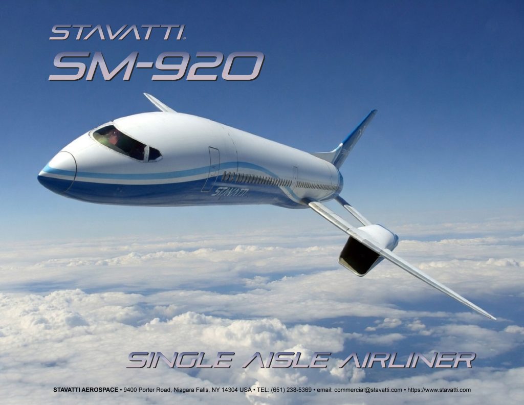
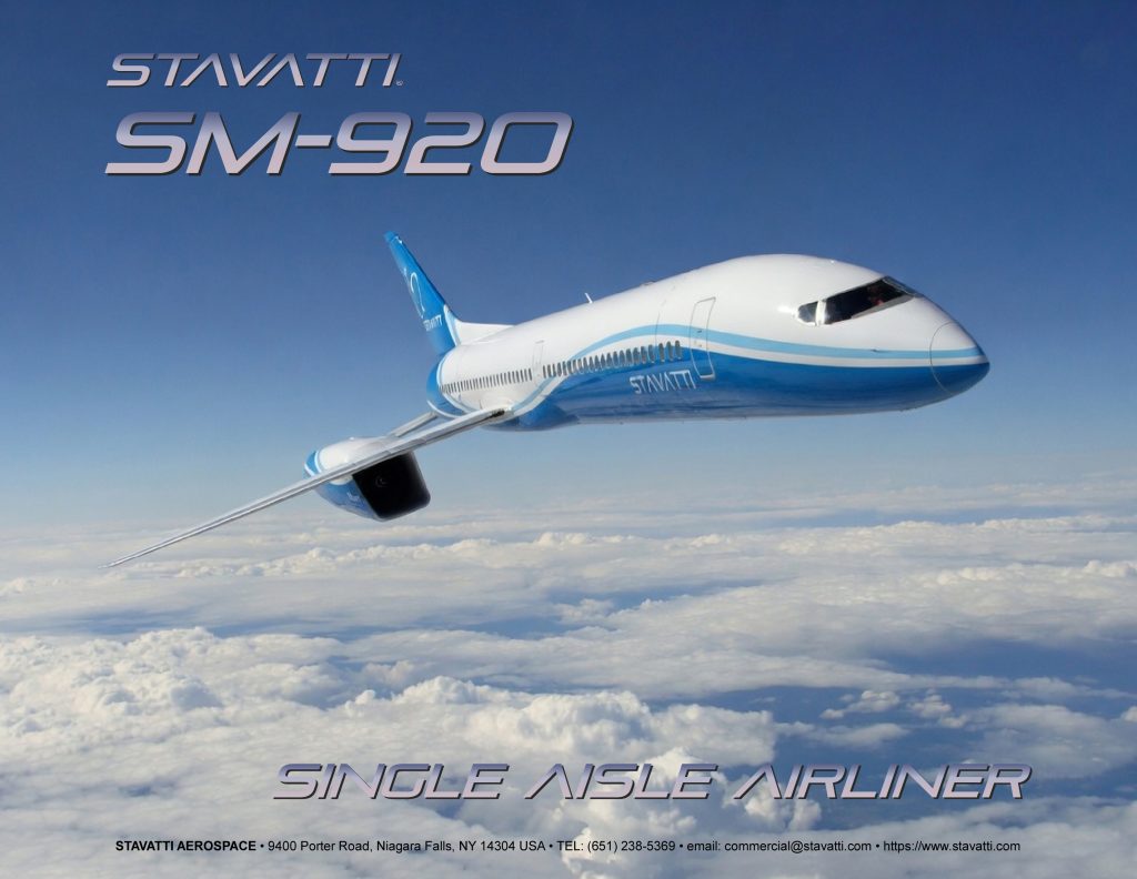
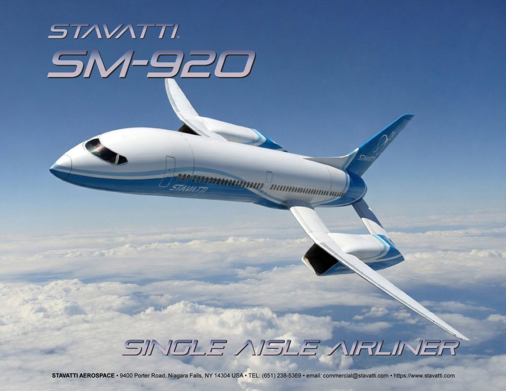
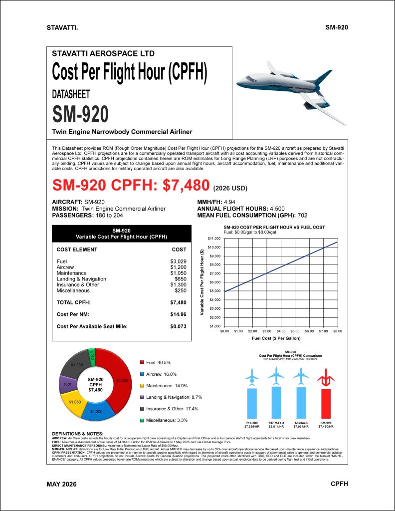
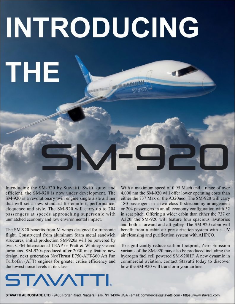
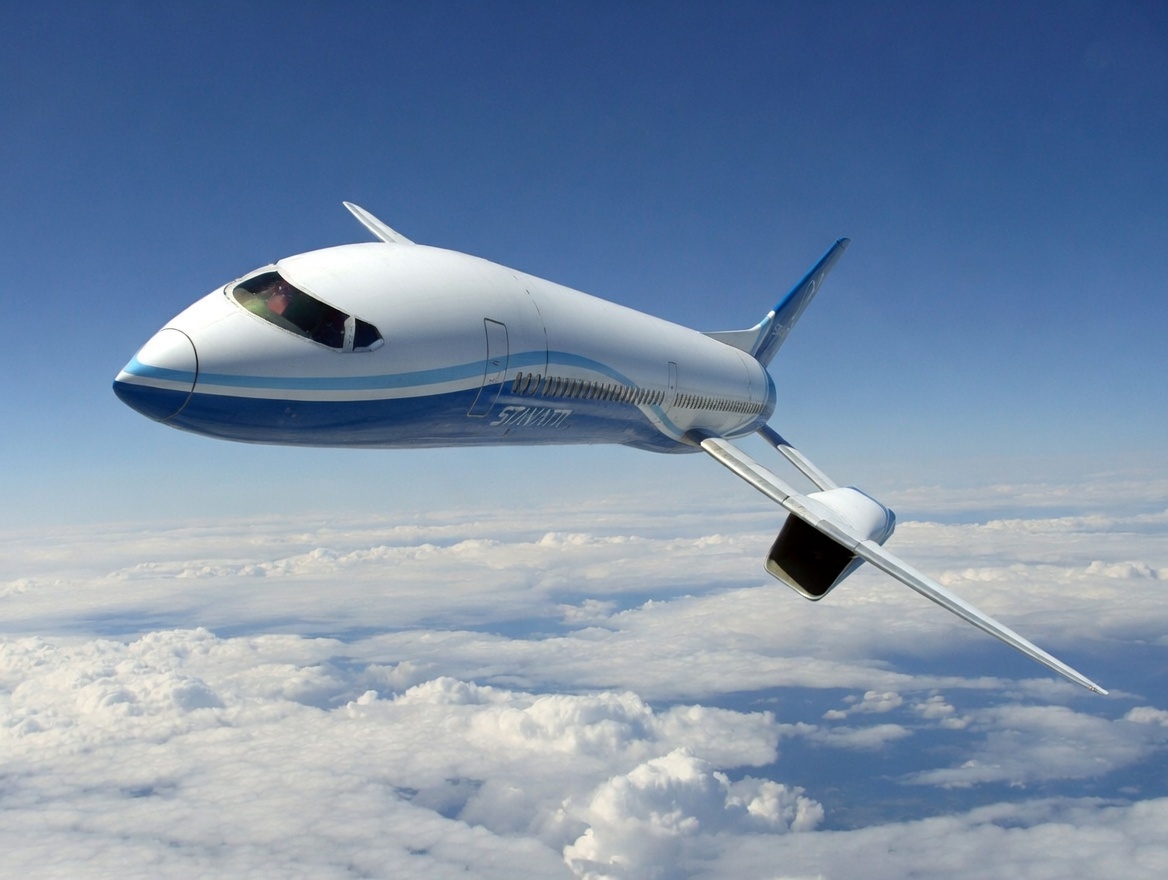
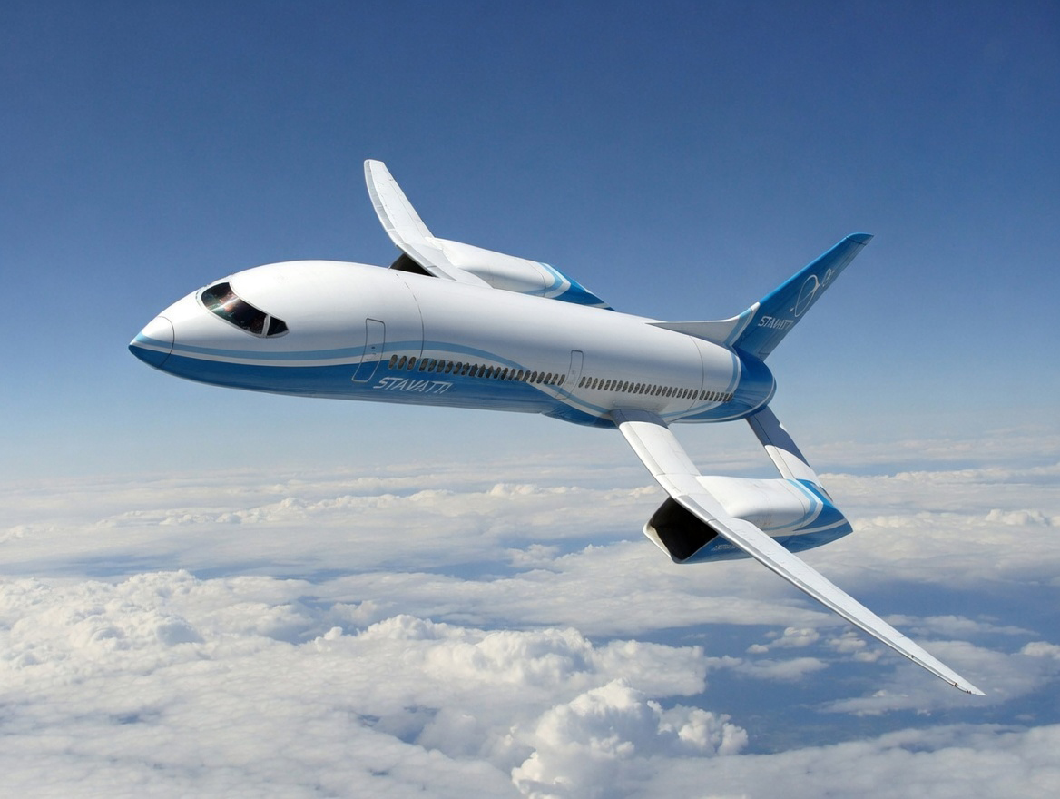
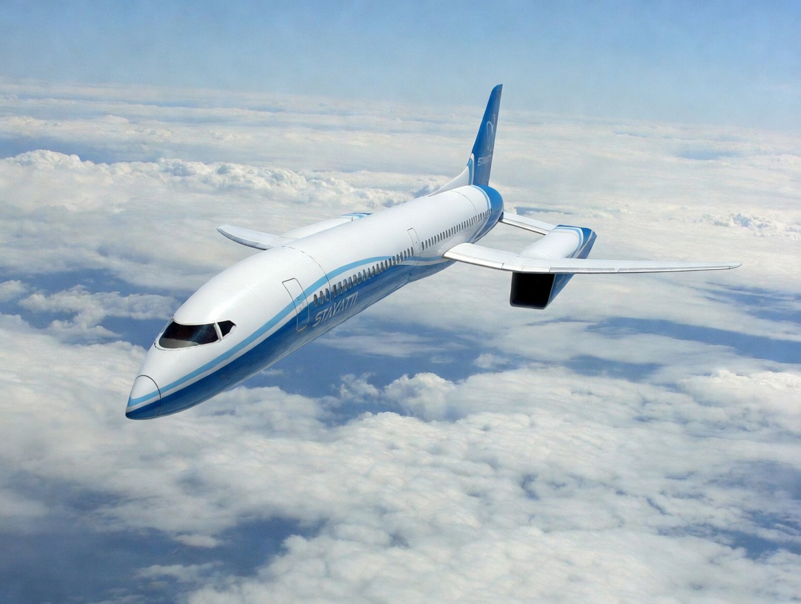
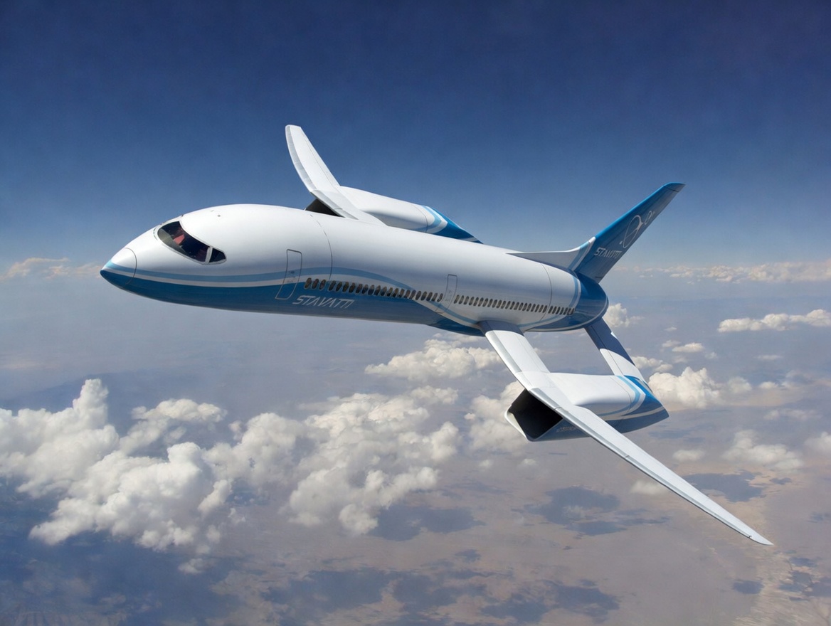
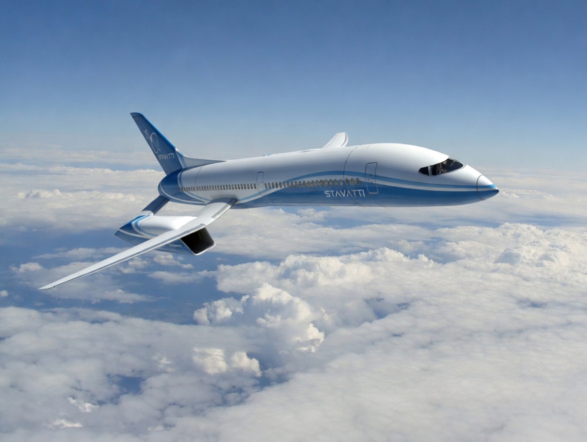
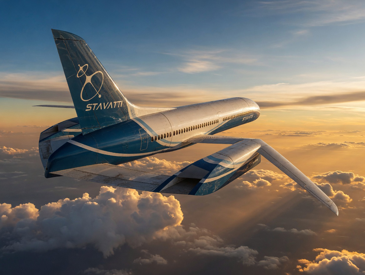
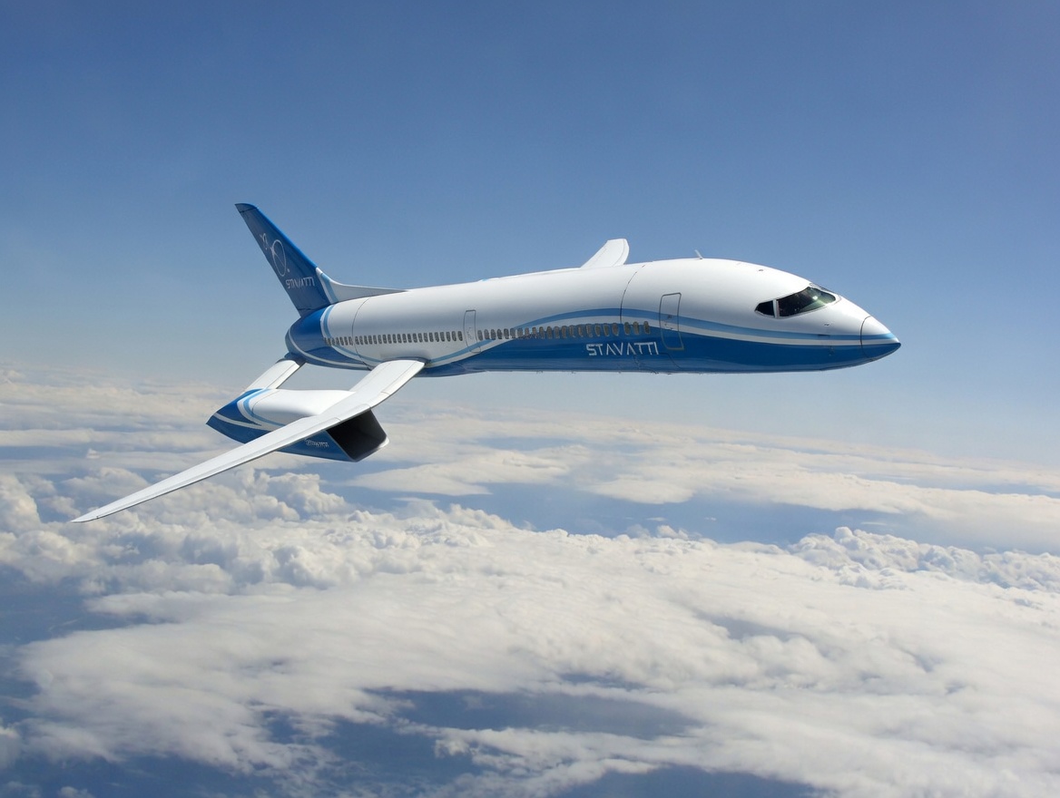
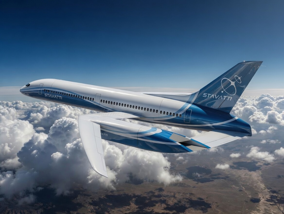
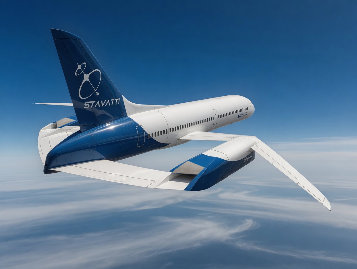
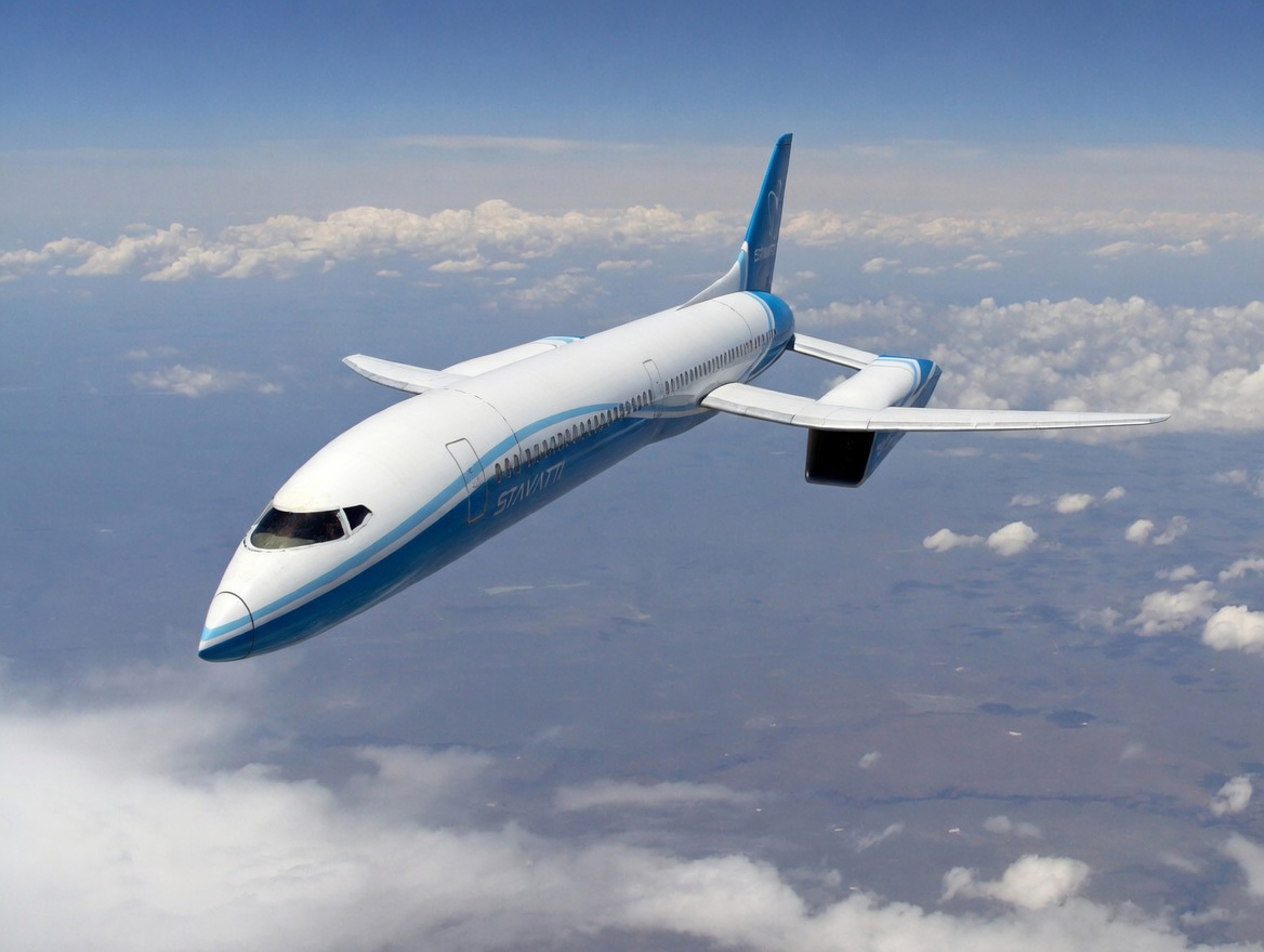
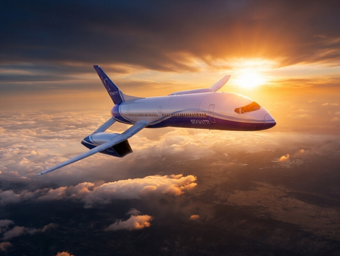
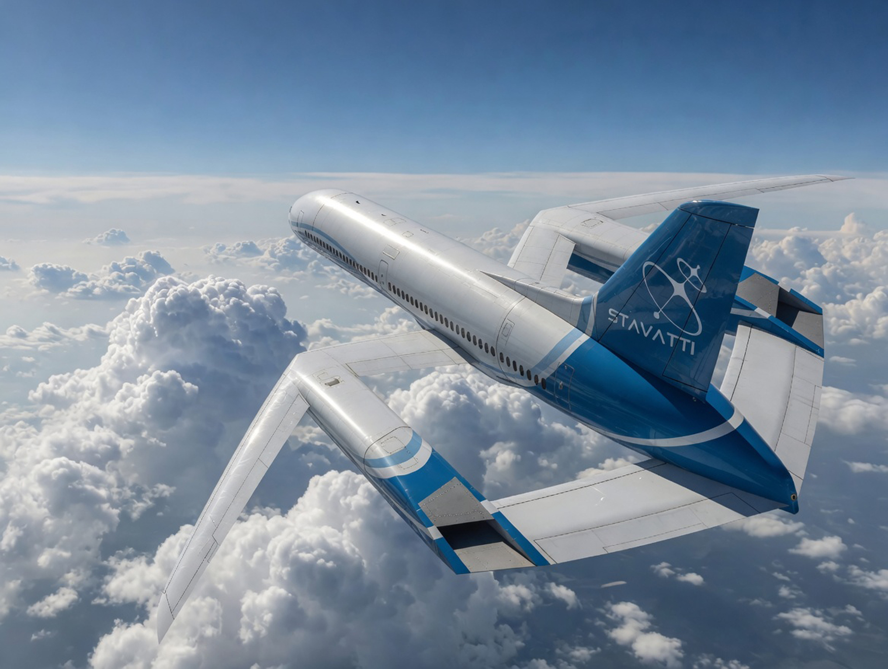
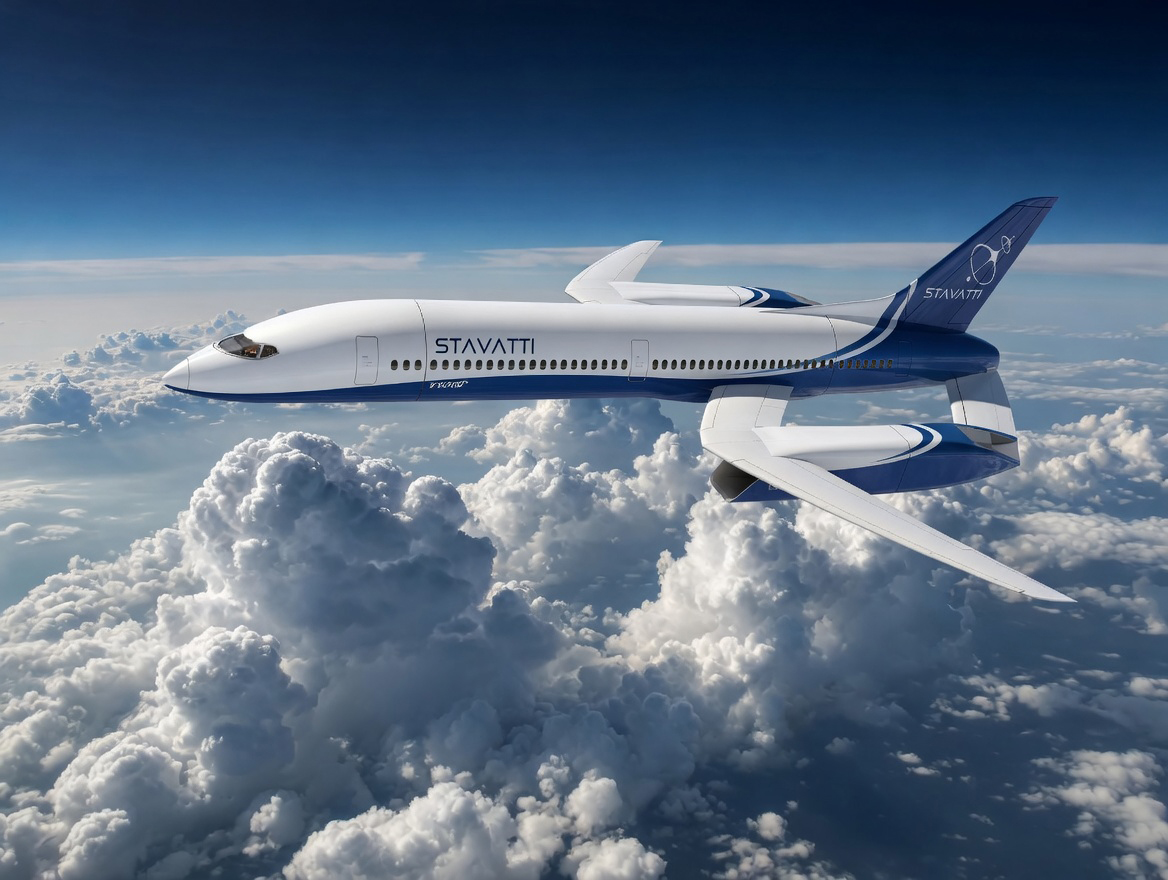
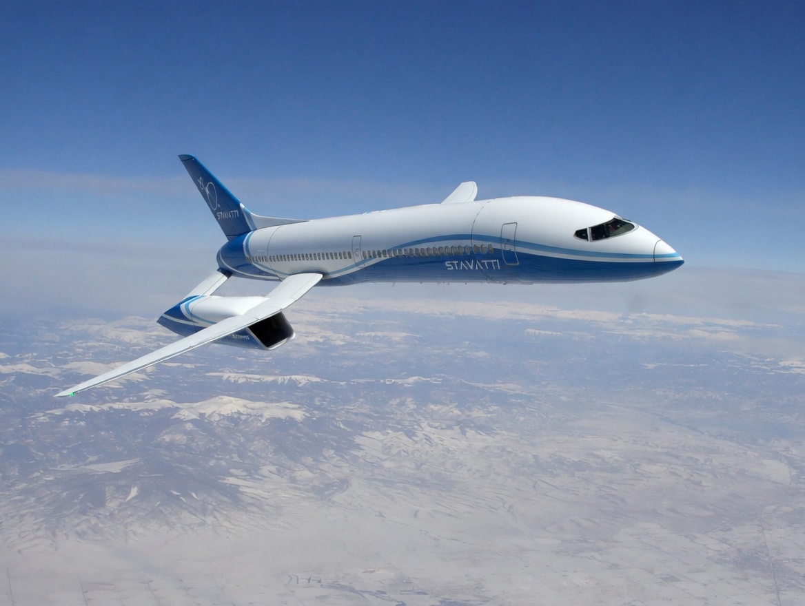
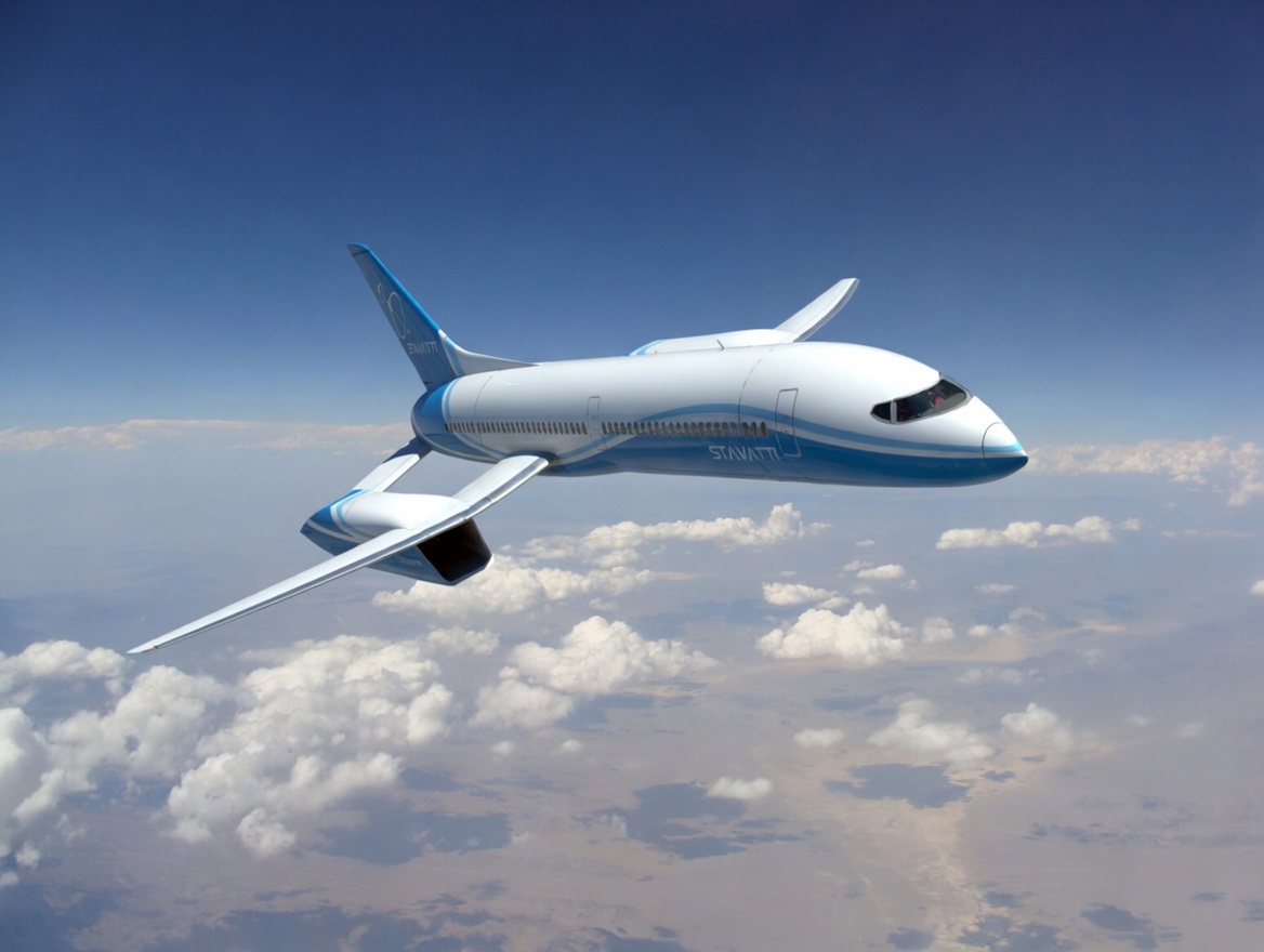
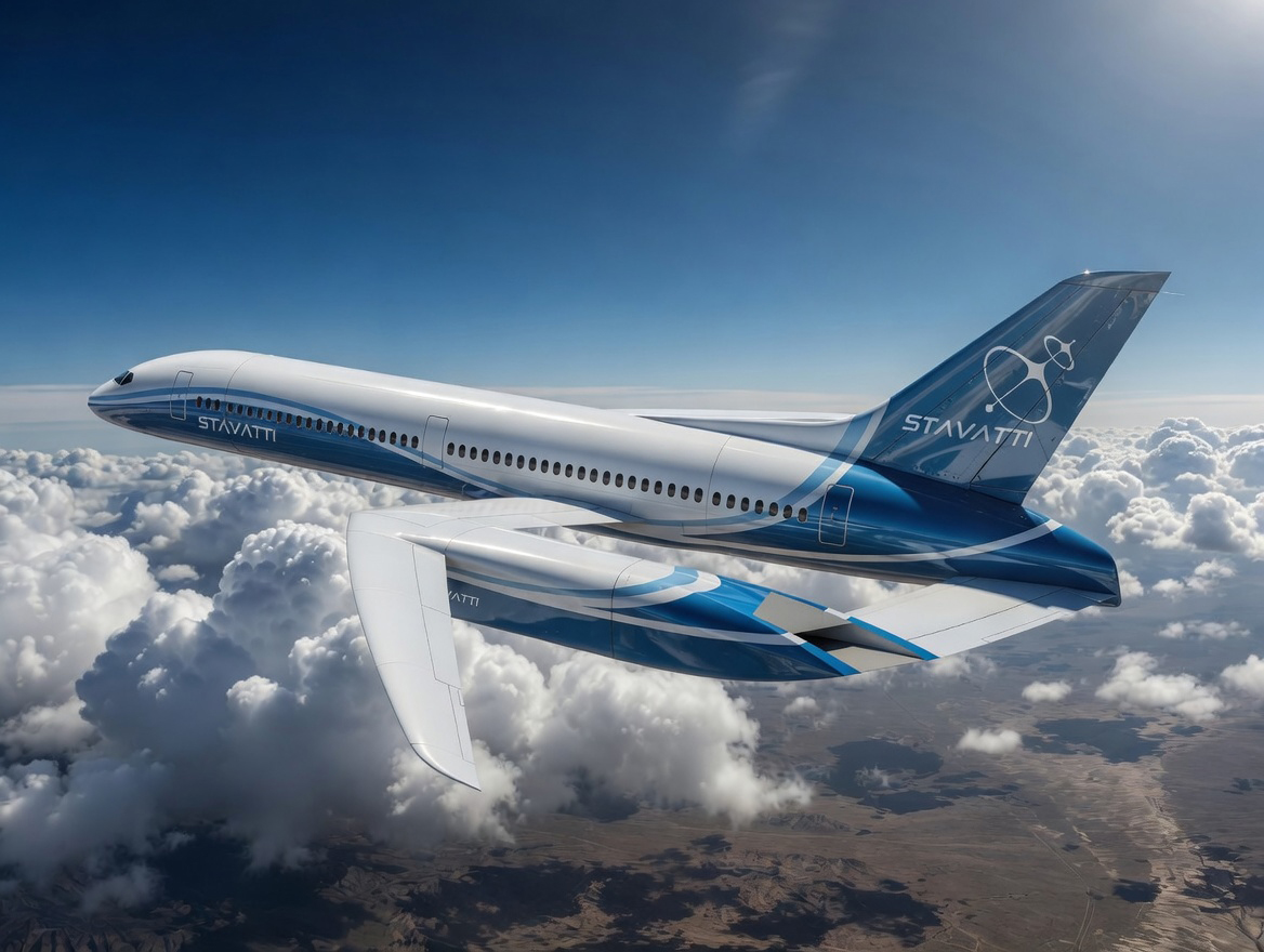
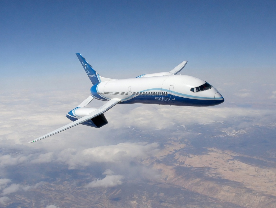
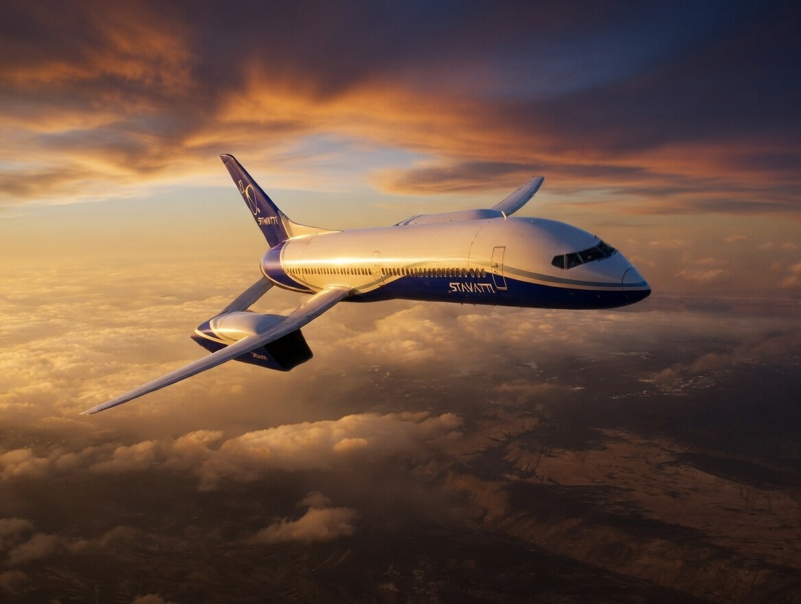
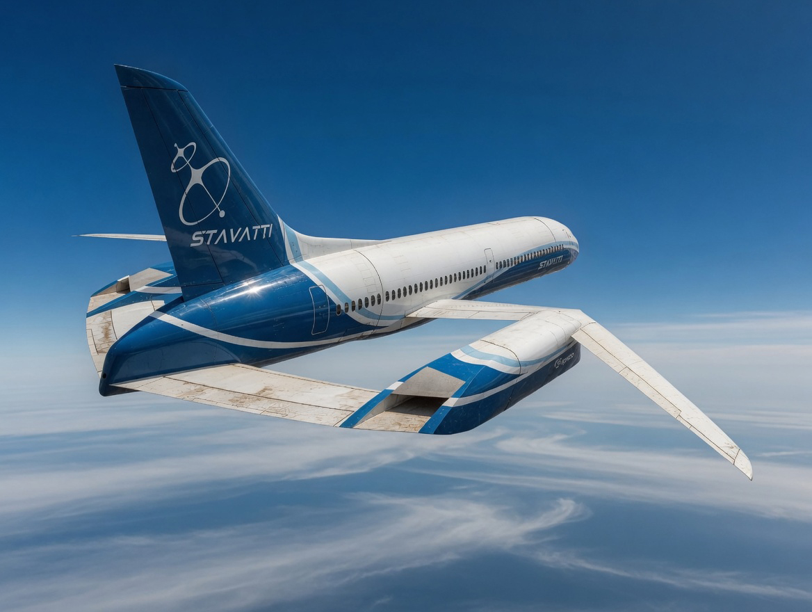
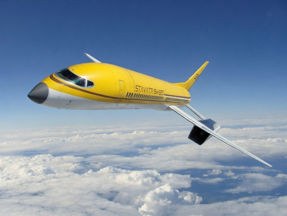