Overview
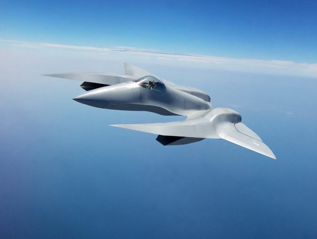
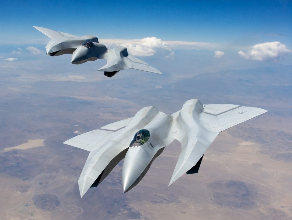
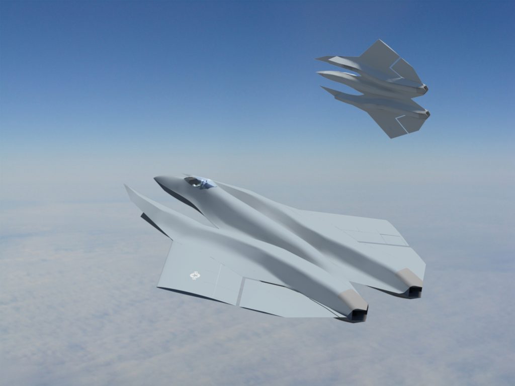
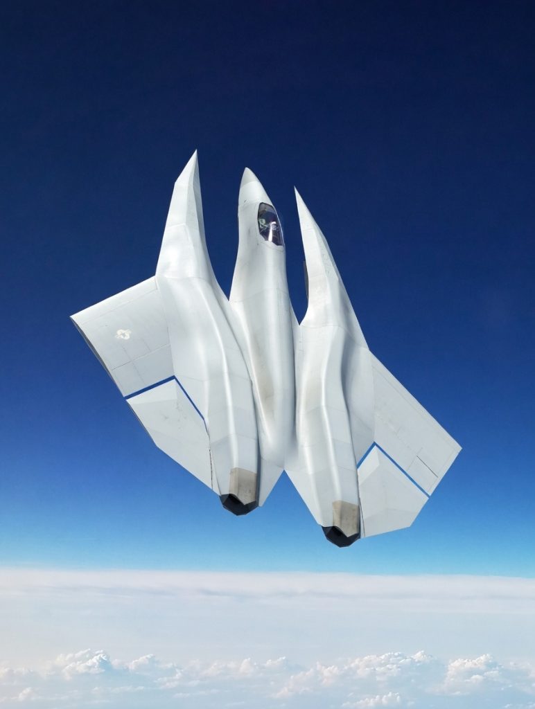
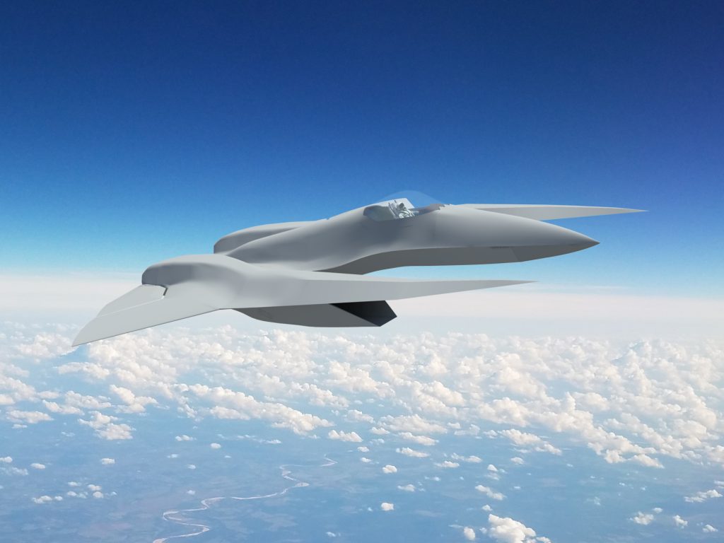
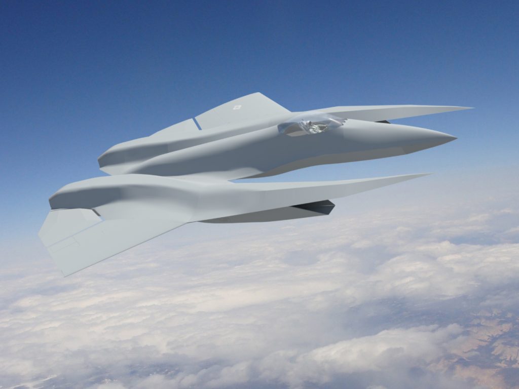
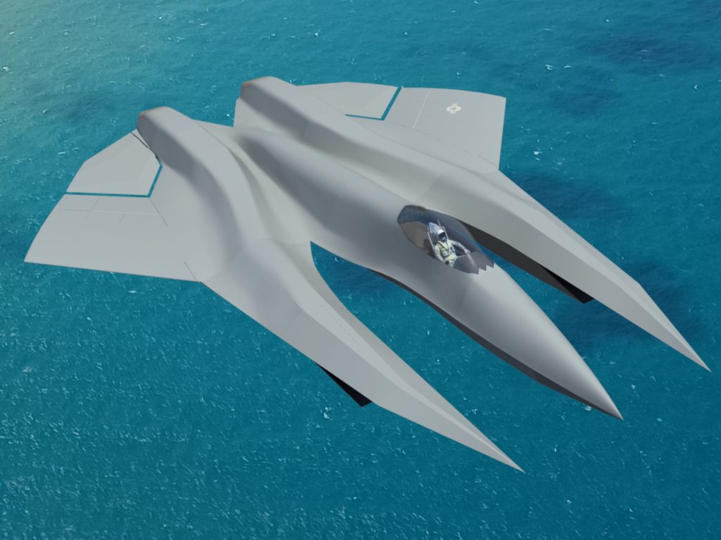
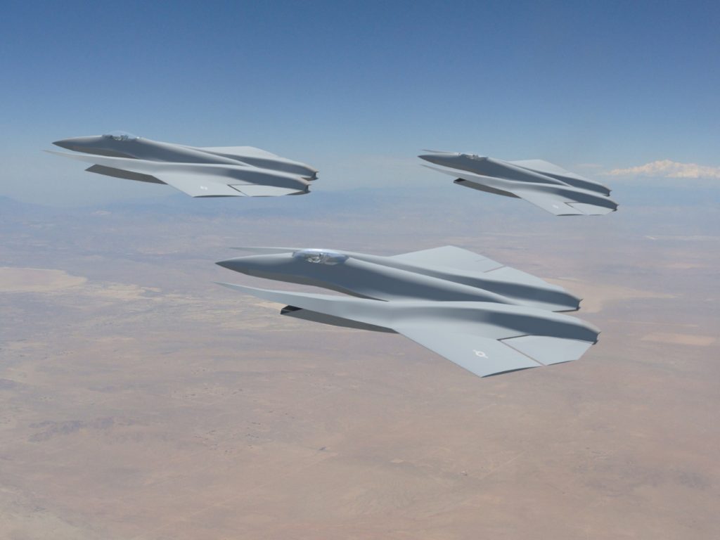
The SM-39 is a next generation air dominance fighter and fighter-bomber. Designed to perform the missions of the F-47, F-22, F-15, F/A-18E/F and the now retired F-14 Tomcat, A-5 Vigilante and A-6 Intruder, the SM-39 is a twin engine, piloted or unpiloted autonomous, low observable aircraft. With two internal weapon bays, all moving horizontal stabilizers with no vertical tail, double slotted flaps with boundary layer blowing, thrust vectoring nozzles and titanium foam metal sandwich construction, the SM-39 is a sixth generation fighter and a direct bridge between atmospheric aircraft and future reusable space fighters.
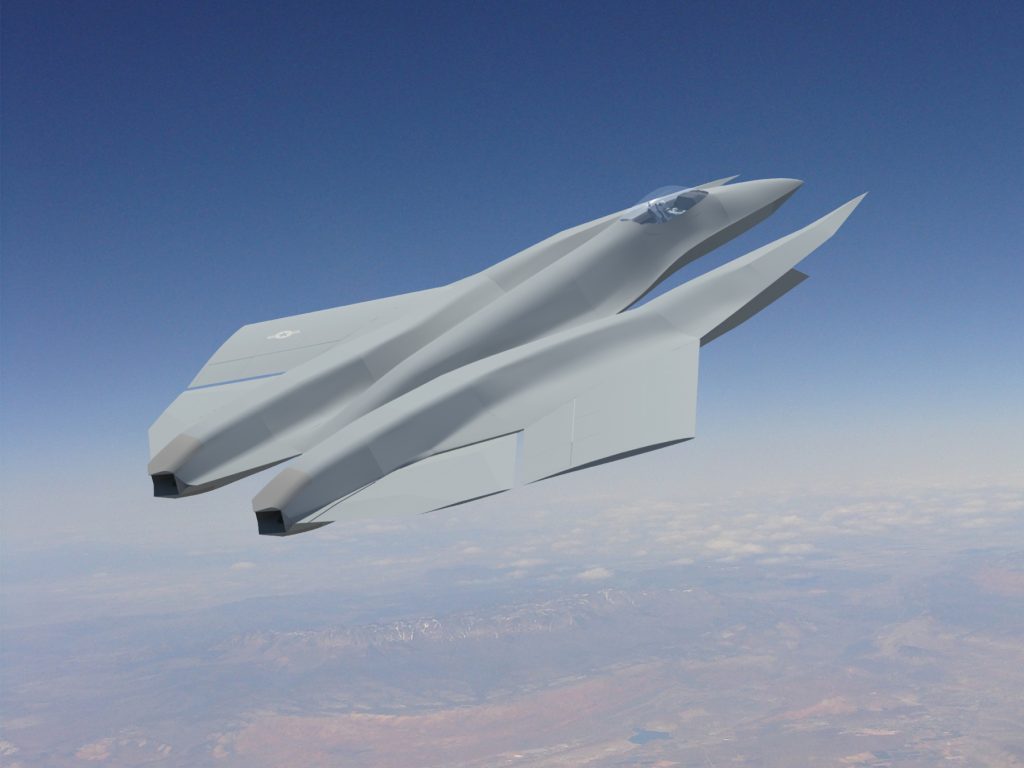
Of radical planform, the SM-39 is a triple fuselage design featuring a streamlined center, high fineness ratio primary fuselage accompanied laterally by right and left mounted secondary fuselages. The secondary fuselages begin as highly swept wing strakes into which the aircraft wing, empennage, an a single ventral air intake and engine nacelle is blended. This planform configuration results in a significant reduction in supersonic wave-drag, allowing the aircraft to have a volume distribution that is very near the Sears-Haack ideal. Designed for supercruise, this configuration places the wing leading edge within the shock cone of the secondary fuselage wing strakes at high Mach numbers.
In addition to reducing wave drag, the SM-39’s triple fuselage design allows for a an efficient distribution of primary aircraft systems. The center fuselage houses principal avionics, including the radome and AESA radar, as well as the cockpit, nose landing gear and two internal weapons bays. The secondary fuselages are home to a high pressure recovery, serpentine variable geometry internal compression air intake, a single variable cycle afterburning powerplant and the main landing gear. Both the center and secondary fuselages house internal fuel tanks, sensors and electronic countermeasures. Distributing aircraft systems laterally as well as longitudinally, the three fuselages result in greater internal volume with lower overall wave drag than any supersonic fighter in service today.
Designed for airspeeds in excess of Mach 4, the SM-39 will be powered by two 50,000 lb class afterburning powerplants. These engines will be next generation variable cycle powerplants such as the GEAE Adaptive Cycle Engine (ACE) designed for high speed, supersonic operations and efficient cruise. The current baseline design features a new design variable cycle turbofan-turbojet that benefits from a titanium diboride cermet compressor, combustor and turbine stage that allows TITs as high as 4,400° F, resulting in a maximum static thrust of 52,400 lbs with an SFC of 1.35. Cruise SFC of this new engine is predicted at values as low as 0.53. Maximum military thrust is projected at 42,700 lbs. This new design engine, designated the E1400 VCE will be developed, qualified and produced by a new aircraft engine company tentatively known as NeoThrust™ in joint venture with Stavatti. Incorporating a low observability afterburner, the E1400 benefits from a thrust vectoring nozzle to enhance maneuvering.
For continuous high speed operations and a corrosion resistant 75 year operational life, the SM-39 will have non-carbothermic titanium diboride metal sandwich skins with a titanium diboride foam metal core.
This nearly monocoque structure will be supported by an internal framework of laser welded titanium frames, bulkheads and longerons.
Pioneering new approaches in aerodynamics, airframe structures, efficient variable cycle turbine propulsion, active low-observability and boundary layer control and integrated avionics, the SM-39 is a Mach 4.0+ fighter capable of level supercruise speeds in excess of Mach 2.5 while maintaining a stall speed as low as 103 KTAS in the landing configuration. With a typical per unit flyaway cost of $85 Million, the SM-39 will be competitively priced and offer significant cost savings over same class aircraft. The SM-39 is now under development and will be qualified and certified to MIL-HDBK-516B Airworthiness Certification Criteria in accordance with AFPD 62-6 and AFI 62-601 at the AFFTC, Edwards AFB. The SM-39 will also be certified to applicable FAA type and production certification standards as a fully qualified Day/Night VFR and IFR (VMC/IMC) aircraft.
Accommodation
Benefiting from a modular cockpit, the SM-39 will be produced in single (SM-39S), two-seat tandem (SM-39T) and unpiloted/autonomous (SM-39U) configurations.
The SM-39S/T cockpit is designed to accommodate a wide spectrum of male and female crewmembers accommodating JPATS Cases 1 through 8 encompassing the 1st percentile female through the 99th percentile male (NATO) population range. This population range corresponds to crewmembers ranging from 4 ft 10 in/100 lbs through 6 ft 5 in/280 lbs. For planning purposes, assumed standard crew-member weight is 260 lbs, including survival equipment.
The SM-39S/T flight crew includes a single pilot seated on a MK18 or ACES 5 zero/zero ejection seat. In satisfaction of the Tactical Strike role, a two seat tandem SM-39T will also be produced featuring a student and instructor seated in tandem (fore and aft crewstations respectively) or as a Strike Fighter a Pilot and Weapon Systems Officer (WSO) seated in tandem. SM-39S/T crewmembers are seated on MK18 or ACES 5 zero/zero ejection seats or proprietary ejection seats based on the K-36D under license by a US manufacturer. Alternatively the SM-39 may feature proprietary escape pods for high speed/high altitude survival.
Autonomy
The SM-39 Razor will be produced in both piloted and dedicated unpiloted autonomous/remotely piloted drone configurations. As a foundational design feature, all production SM-39 aircraft will be capable of autonomous flight operations. Piloted variants will contain single or two seat cockpit modules yet can be flown with or without human pilots. Dedicated unpiloted SM-39Us will feature identical autonomous flight control systems, but the cockpit module will be replaced with additional fuel tanks for increased range, additional optical solid-state computer memory systems for flight data/flight event recording and larger antennas for communication and secure data-link. Drone and Autonomous SM-39Us will serve in a variety of roles including interceptor, fighter-bomber, interdictor, strike, reconnaissance and loyal wingman.
Drone and Autonomous SM-39 variants (SM-39U) will employ a Stavatti proprietary Synthetically Intelligent (SI) unpiloted autonomous flight control architecture which will combine a Vehicle Flight/Mission Management System with Power-By-Wire (PBW) flight control systems, an integrated sensor and navigation suite and Synthetic Intelligence to command both aircraft flight controls, weapons and electronic warfare systems. The SM-39U Autonomous Flight Control Technology (AFCT) is derived from Stavatti open architecture unpiloted air vehicle systems model that focuses heavily upon Synthetic Intelligence systems by Stavatti Industries Ltd and partner companies as our organic in-house Artificial Intelligence (AI) Solution.
To improve aircraft safety, survivability and ensure mission completion and success, Stavatti is developing an open architecture flight control architecture which integrates Power-By-Wire flight controls, sensors, GPS/INS navigation, electronic countermeasures, weapon systems and an autonomous logic suite to arrive at a flexible, Line Removable Unit (LRU) type standard flight control system for military aircraft.
These systems will then be integrated with Stavatti Synthetic Intelligence (SI) to result in a truly autonomous, self-identifying aircraft. The basis for Stavatti’s autonomous and robotic products, the key differential between Stavatti and competitor autonomous aircraft will be the use of Synthetic Intelligence. Through this approach, Stavatti will produce an aircraft that will augment and enhance a pilot’s ability to deploy the aircraft in the most efficient, safe and tactically effective manner while resulting in a quasi thinking aircraft that is capable of satisfying multi-domain objectives in a threat saturated environment.
Powerplant
The SM-39 will be powered by two next generation air breathing, thrust producing turbo-powerplants. Each powerplant will provide at least 50,000 lb sea-level static thrust with augmentation and up to 40,000 lbs thrust at maximum dry/military power. Total aircraft sea-level static thrust will be at least 100,000 lbs augmented and up to 80,000 lbs dry/military. The SM-39 will have a much broader flight envelope than an F-15, F-22, F-35 or Su-27. Capable of sustained flight operations between 103 KTAS and 2,005 KTAS, the SM-39 is designed to be superior to 5th generation fighter aircraft at both very low (post stall) and very high speeds. To enable sustained flight operations at Mach 3.0 to Mach 4.5 and service ceilings of between 70,000 and 120,000 ft, Stavatti is looking ahead at new, next generation powerplants designed specifically for the Razor’s flight regimes.
For the purpose of engineering the SM-39 airframe, two possible powerplants of similar physical size and configuration have been envisioned for the aircraft. Those powerplants include the General Electric Aircraft Engines (GEAE) Adaptive Cycle Engine (ACE), and the NeoThrust E1400 VCE. In moving forward with initial conceptual design, the SM-39 as described herein features two hypothetical Stavatti E1400 VCE afterburning powerplants each delivering 52,400 lbs maximum static thrust at SL. The SM-39 may, however, be equipped with GEAE ACE engines or production derivatives thereof.
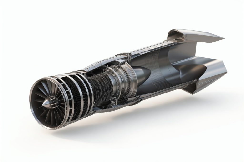
The E1400-NT-520 is a next generation variable cycle afterburning turbofan/turbojet engine and a member of the E1400 powerplant family. Producing up to 52,000 lbs of static thrust at sea level, the E1400 is designed to power supersonic aircraft to airspeeds in excess of Mach 3.0 and to altitudes of 100,000 ft. The E1400 combines the advantages of the turbojet (high specific thrust) with those of a turbofan (low specific fuel consumption and reduced noise).
A third generation variable cycle engine, the E1400 builds upon the proven architecture of the P&W J58 (A-12, SR-71) and the GEAE YF120 (YF-22, YF-23) to result in a variable bypass/variable cycle gas turbine engine. The E1400 is being designed by Stavatti as a powerplant for the SM-36 and SM-39. The engine will be produced by the NeoThrust™ Division of Stavatti Industries or under license by an Industry Team Member with production coinciding with SM-36/39 production. The E1400 will be built in the USA with all components and superalloy raw materials sourced domestically in the United States.
The E1400 benefits from two Variable Bypass Injectors (VABI). The first VABI is a selector valve located downstream of the fan which controls flow through the the bypass inlet. When open, the engine functions as a turbofan with a maximum bypass ratio of 0.54. When closed, the engine functions as a turbojet with all airflow from the fan being directed through the compressor. The second VABI is located aft of the turbine module and serves as a variable area bypass nozzle to inject secondary flow into the core stream.
Designed for high speed, high temperature operations, the E1400 is benefits from advanced materials including TibTek™ Non-Carbothermic Titanium Diboride cermet materials. TibTek™ is used throughout the engine including the engine inlet and fan, compressor, combustor module, turbine, afterburner and in bearings.
A mixed flow, two shaft afterburning engine, the E1400 has seven modules plus an accessories gearbox. The fan module features a three-stage, three rotor, long chord blisk fan with 17 variable inlet guide vanes. The fan module is mounted to the engine mid-frame which houses the forward engine mounts, eight support struts, the bypass inlet and the bypass inlet VABI selector valve. The compressor module consists of a six stage, dual rotor counter-rotating axial flow high pressure compressor with three rows of variable stators. The combustion chamber module consists of a high temperature annular combustor with two ignitors and 20 fuel nozzles.
The turbine module includes a single high pressure turbine to drive the compressor and a single low pressure turbine to drive the fan. The turbines are of counter-rotating axial flow type. Composed of TibTek™, Turbine Inlet Temperatures (TIT) of over 4,500° F are realized, allowing greater thermodynamic efficiency than any turbofan in its class. The engine is equipped with a low radar observable afterburner and afterburner duct. The engine exhaust nozzle used in the SM-39 is a two-dimensional pitch-vectoring convergent/divergent nozzle.
Air Intakes
Implementing the Willy Messerschmidt approach of “wrapping the smallest airframe possible around the largest engine,” the SM-39 combines stunningly powerful derivative engines with an air intake system designed to strain every ounce of thrust out of the combined powerplant/intake propulsion system. Featuring two advanced air intakes, each SM-39 air inlet feeds a single engine.
Designed for mass flow rates of 360 lb/sec to 400 lb/sec, the air intakes are of serpentine type characterized by an overall length of 30 ft, equivalent to more than seven powerplant diameters. Each air intake offers a capture area of 2,400 sq in and is mounted ventrally below the aircraft’s leading edge strakes. Implementing this valuable lesson learned from the F-16 and F/A-18, the inlets will deliver favorable airflow to the engine at high AoA. This intake arrangement enables super-maneuverability with reduced potential for compressor stalls.
A variable geometry inlet designed to achieve high pressure recoveries at Mach numbers greater than 2.0, the SM-39 intake will employ low-observable internal compression technologies to result in dynamic intake airflow management throughout the flight regime. The air intake will be equipped with a boundary layer air diverter and bleed air doors for air flow management. Excess intake mass flow as supplied the intakes will be fed through a proprietary Regenerative Ram Air Diverter (RRAD) duct which envelopes the powerplant to reduce propulsion system thermal signature.
Armament
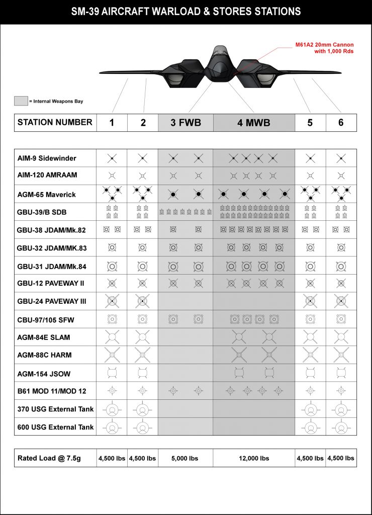
The SM-39 air weapon system will deliver a wide array conventional and nuclear weapons, satisfying both air-to-air and air-to-ground modes. Baseline aircraft will be equipped with traditional fixed internal armament including one 20mm M61A2 Vulcan cannon. The SM-39 will have 1,000 rounds of 20mm ammunition carried within an ammunition drum derived from the F-15C ammo drum/feed system.
Expendable stores and ordnance may be carried internally (for enhance aerodynamic efficiency and low observability) as well as externally. For internal weapons carriage, the SM-39 will be equipped with two internal weapons bays: A Forward internal Weapons Bay (FWB) and a Mid-fuselage internal Weapons Bay (MWB). The FWB is directly behind the nose landing gear and below the cockpit module. Measuring 162 in long, 46 in wide and with a mean height of 34 in, the FWB can carry a variety of stores on two vertical pneumatic ejector racks including two AIM-120Cs or two AGM-65s or two GBU-31s. The FWB is rated to a maximum payload of 5,000 lbs at 7.5-g.
The MWB is located in the aircraft mid-fuselage between engine air intakes. The MWB measures 174 in long, 65 in wide and has an average height of 68 in. The MWB can be equipped with vertical ejector racks or a rotary launcher. When equipped with a rotary launcher, the MWB can carry up to six AIM-120Cs or five GBU-31s. The MWB is rated to a maximum payload of 12,000 lbs at 7.5-g. With the rotary launcher/bomb racks removed, the MWB may be fitted with a custom configured “ferry tank” to provide up to 12,000 lbs of additional fuel for long range ferry flights in the clean configuration.
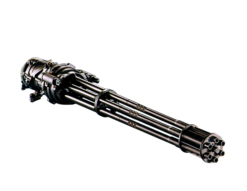
The standard SM-39 cannon is the General Dynamics M61A2 20mm Vulcan cannon. The M61A2 is a six-barrel, electro-mechanical actuator driven cannon with a rate of fire of 6,000 rds/min to 7,200 rds/min. Cannon dispersion is 8 miliradians in diameter/80 percent circle. The M61A2 employs standard 20mm PGU-28/B ammunition. The SM-39 is armed with 1,000 rds of 20mm ammunition contained within a titanium drum magazine.
Located the aircraft fuselage, the cannon will be equipped with a retractable muzzle cover. The cannon is fitted with twin recoil adapters to dissipate firing forces. The aircraft features an Automatic Gun Targeting System (AGTS) which allows the aircraft targeting computer to guide and control the aircraft though its Power-By-Wire (PBW) flight control system upon designation of a specific gun target. When selected, the AGTS assumes momentary interruption of pilot flight control to assure positive lethal engagement of the target with minimum expenditure of ammunition.
In the ATGS mode aircraft wing and tail flight control surfaces and aircraft thrust vectoring are applied in concert to enable the aircraft to maneuver as a Control Configured Vehicle (CCV).
External stores may be carried on four external wing hardpoints. Each hardpoint is rated to 4,500 lbs. The external hardpoints will be jettisonable and will increase overall aircraft signature. The external hardpoints will be qualified to carry a wide variety of stores including the GBU-24, AGM-84, AGM-88, AGM-154 and both 370 and 600 gallon external fuel tanks.
Total rated combined design internal and external warload is 25,000 lbs. Typical warload for the air-to-air mission consists of eight AIM-120Cs at a nominal weight of 3,000 lbs. Weapons will be integrated using a MIL-STD-1760 Weapon Interface Data Bus. The SM-39 is designed to carry 25,000 lbs of warload with 30,000 lbs of internal fuel at an MTOW of 95,000 lbs for land-based operations. Maximum design load factor at 95,000 lb MTOW is 6.3-g. For naval carrier operations, the MTOW is reduced to 80,000 lbs allowing a 25,000 lb warload with 15,000 lbs of fuel or a maximum warload of 10,000 lbs with 30,000 lbs of internal fuel. Maximum design load factor at carrier MTOW is 7.5-g. An abridged SM-39 stores loading chart is provided:
Directed Energy Weapons
Providing significant combat capability, the SM-39 may be equipped with a variety of Directed Energy Weapons (DEW) including those under development by Northrop Grumman. The Northrop Grumman Gamma or a derivative thereof is a potential DEW system for the SM-39. A member of the Firestrike family, the Gamma is a 13.3 kW range laser that employs ruggedized solid-state technology on a LRU basis to provide energy levels greater than 90 kW. Employing compact 400 lb LRUs Gamma is one possible option from which a contractor provided DEW may be integrated into the SM-39.
Providing an organic DEW solution, Stavatti is developing a Gas Dynamic Directed Energy Weapon as an alternative to the standard fixed internal 20mm cannon. Consisting of a Gas Dynamic Laser (GDL) this advanced system would serve as a lethal energy weapon for air-to-air and air-to-ground engagements.
A directed beam energy weapon, the GDL generates a lethal laser beam through the thermal pumping of a mixture of Carbon Dioxide, Nitrogen and Helium gases. Initially contained at a state of high temperature, high pressure thermal equilibrium within a gas reservoir, triggering of the weapon results in the acceleration of the gas mixture through an annulus to achieve local sonic flow. The high speed gas mixture then enters a supersonic expansion nozzle, which significantly reduces both the pressure and temperature of the gas, while further accelerating the flow to a hypersonic velocity.
The result is a rapid expansion within the relaxation time of the upper and lower vibrational energy states of the gas mixture, inducing the vibrational freezing of the gas molecules and the subsequent generation of a high energy laser beam within a resonance chamber. Focused with primary and secondary mirrors within the resonance chamber, a lethal high-energy beam of laser light will be produced that may be directed to a specified target.
The SM-39 GDL will be mounted within the aircraft wing or fuselage structure and will feature a resonance chamber. The lethal laser beam will be directed from the resonator through either a fixed optical guidance system through which it is projected from the aircraft to the target. The projected weapon range is between 1 and 10 nm with an output to target greater than 150 kW.
Stavatti has considered a number of GDL configurations for direct integration into fixed wing turbofan aircraft. One potential configuration includes a direct incorporation of key GDL weapon elements into a specifically engineered powerplant afterburner duct whereby the thermal energy of the turbofan powerplant will be used to thermally pump a lasing gas mixture within the afterburner duct, resulting in laser beam formation perpendicular to the gasflow and out of the engine. The laser beam is then optically directed to a direction parallel to the engine afterburner duct and projected from the aircraft to the target. This particular configuration was previously envisioned in various embodiments including Patent 5,384,802.
A second GDL configuration draws hot bleed air from the turbofan powerplant to heat an adjacent resonance chamber. This resonance chamber will be pressurized with lasing gases which upon weapon firing will be exhausted through a dedicated diffuser and weapon exhaust nozzle. Lethal beam energy will be optically directed from the resonance chamber to the intended target. All SM-39 GDL configurations use heat provided from the hot gases of the aircraft powerplant to provide the energy necessary to thermally pump the weapon gas mixture.
To fuel the weapon pressurized helium will be carried on-board the aircraft to be replenished on the ground. Weapon carbon dioxide and nitrogen will be generated and compressed in-flight using an on-board compressor that works in conjunction with powerplant bleed air.
The lethal beam is then optically directed to a fixed laser weapon port (as in the case of a dedicated 20mm cannon replacement) and/or to a rotating turret that can be used as both an offensive and defensive weapon, providing a countermeasure against air-to-air missiles.
The GDL is not a chemical laser, nor does it require electrical energy generated by the aircraft. It is a gas dynamic weapon that shares mechanical design similarities with rocket engines and supersonic wind tunnels. A very cost effective lethal laser weapon system that offers a high power-to-weight ratio, the GDL takes heat generated by the SM-39 powerplant and converts it into a effective energy weapon that could replace both fixed internal cannons as well as some short range AAMs. Bench tested and successfully operated at the Avco Everette Research Lab in 1966, the GDL has decades of research behind it and is a low-risk, high energy pathway to achieving a pragmatic DEW system.
Avionics & Sensors
The SM-39 will have an integrated sensor and avionics suite benefiting from Open System Architecture (OSA) to allow the integration of a variety of sensor and avionic systems. Avionics and sensors will be integrated about a MIL-STD-1553B Interface/Data Bus. Featuring a comprehensive avionics and sensors suite, the philosophy driving the SM-39 avionics configuration focuses upon capability, reliability, flexibility and ease of serviceability. Incorporating both avionics designed or modified to meet specific SM-39 needs as well as proven Military or Commercial Off-The-Shelf systems (MOTS/COTS), standard core SM-39 avionics include the Power-By-Wire (PBW) Flight Control System, Air Data Computer, Flight Management System, Avionics Management System, Automatic Flight Direction System, Instrument Landing System, Secure Data Link, Voice/Data Recorder and emergency power supply.
The SM-39 will be offered with both a Standard Production and a Prototype/Export avionics configuration. In the Standard configuration, avionics and sensors are optimized to coincide with aircraft that can be operated primarily by the United States (USN, USAF, USANG, etc.). The Standard configuration features sensors, avionics and EW/ECM systems that may be developed specifically for the SM-39 under contract for Stavatti or internally by Stavatti’s Avionics and Sensors Division. In the Export configuration, aircraft avionics and sensors are configured to use an off-the-shelf solution that is approved to export from the USA to allied customers worldwide. Prototype and Initial Production aircraft may have Export Configuration Avionics and Sensors to enable rapid development, production and delivery. A Sensor & Avionics summary table for the Standard Production and Export/Prototype configurations is provided:
| AVIONICS SYSTEM | PROTOTYPE | EXPORT | USA & NATO |
|
| SENSORS | ||||
| Multi-Mode Radar | RACR AESA | RACR AESA | ARACR AESA | |
| IRST | IRST 21 or EOTS | IRST 21 or EOTS | AETOS | |
| COMMUNICATION | ||||
| VHF/UHF COMM | AN/ASQ-242 | AN/ASQ-242 | ACNI | |
| IFF Transponder | AN/ASQ-242 | AN/ASQ-242 | ACNI | |
| Digital Data Link (Link 16) | AN/ASQ-242 | AN/ASQ-242 | ACNI | |
| Digital Anti-Jam Receiver | AN/ASQ-242 | AN/ASQ-242 | ACNI | |
| Intercom System Control | AN/ASQ-242 | AN/ASQ-242 | ACNI | |
| NAVIGATION | ||||
| Radar Altimeter | AN/ASQ-242 | AN/ASQ-242 | ACNI | |
| INS/GPS | FALCN | FALCN | Advanced GPS/INS | |
| TACAN | AN/ASQ-242 | AN/ASQ-242 | ACNI | |
| ILS/GS/MB | AN/ASQ-242 | AN/ASQ-242 | ACNI | |
| MISSION MANAGEMENT | ||||
| Mission Computer | AMC | AMC | AMC | |
| Avionics Management System | AAMS | AAMS | AAMS | |
| Stores Management System | AAMS | AAMS | AAMS | |
| FLIGHT CONTROL | ||||
| Flight Control System | 4 Channel PBW | 4 Channel PBW | 4 Channel PBW | |
| Automatic Flight Direction System | Digital Autopilot | Digital Autopilot | Digital Autopilot | |
| Carrier Landing System | JPALS |
|
ACNI | |
| DISPLAYS | ||||
| Head Up Display (HUD) | Canopy Embedded Display | Canopy Embedded Display | Canopy Embedded Display | |
| Helmet Mounted Display (HDMS) | Gen III HMDS | Gen III HMDS | Gen III HMDS | |
| Display Processor | ADP | ADP | ADP | |
| Forward Primary Display | AD284 29.0 x 11.0 in | AAD284 29.0 x 11.0 in | AD284 29.0 x 11.0 in | |
| Forward Center Display | AD63 7.0 x 9.3 in | AD63 7.0 x 9.3 in | AD63 7.0 x 9.3 in | |
| Right Secondary Display | AD58 7.2 x 8.0 in | AD58 7.2 x 8.0 in | AD58 7.2 x 8.0 in | |
| Left Secondary Display | AD58 7.2 x 8.0 in | AD58 7.2 x 8.0 in | AD58 7.2 x 8.0 in | |
| MISSION RECORDING | ||||
| Cockpit Voice/Data Recorder | FA2100 | FA2100 | FA2100 | |
| EMERGENCY POWER | ||||
| Emergency Power Supply | PS-855/B | PS-855/B | PS-855/B |
The Avionics listed in the above summary are identified by system designation or description rather than manufacturer. Many of the avionic systems identified in the above table have been produced under contract by a variety of different manufacturers over the course of their production life, hence avionics are cited by designation rather than specific producer. Avionics that may be provided by multiple vendors, or for whom a specific vendor has not yet been selected as the Stavatti vendor of choice, are identified as TBD rather than by a specific system designation.
The SM-39 will be designed with an open Avionics System Architecture (ASA) to allow the integration of a variety of sensor and avionic systems over the course of its 30 to 50 year service life. Rather than design the aircraft around a particular avionic/sensor suite, adequate internal volume and environmental support, including electrical supply, cooling and EMP pulse protection will be provided to enable a change in architecture within five year increments such that electronic technologies, which become obsolete within a five year period, can be readily replaced or updated. The ASA approach fully enables future Depot Level Service Life Extension (SLE) programs that may benefit the aircraft throughout its life-cycle.
Avionics configurations significantly impact the flyaway cost of individual aircraft. The typical flyaway cost of an SM-39 equipped with Prototype/Export sensors and avionics is approximately $85 Million. An advanced SM-39 equipped with Standard Production Configuration AESA radar, integrated IFF and a comprehensive electronic countermeasures suite may have a flyaway cost greater than $85 Million. Customers must discuss overall mission needs with Stavatti to arrive at their optimal SM-39 configuration.
Initial prototype and export production SM-39 aircraft will benefit from a host of proven, off-the-shelf current production sensor and avionic systems as originally developed for the F-22 and F/A-35. Systems including the Raytheon Advanced Combat Radar (RACR) AESA Radar, AN/ASQ-242 CNI and EOTS will serve as standard equipment for Prototype and Export SM-39 Razors. The Raytheon Advanced RACR AESA radar is an advanced fire-control radar regarded as a successor to the AN/APG-77. Core capabilities include advanced air-to-air modes, advanced air-to-ground modes, ultra-high resolution mapping, indication and tracking of multiple air and ground targets, combat identification, electronic warfare and ultra-high bandwidth communications. The SM-39 ARACR AESA will feature more than 2,000 GaAs T/R modules proving significantly longer search, track and low observable aircraft detection ranges than any competing or threat radar. Originally developed as a successor radar for the F-15, F-16 and F/A-18, an advanced derivative variant of the RACR with a wide area antenna array will serve as the fire control radar for prototype and initial production export SM-39 Razors.
The Northrop Grumman AN/ASQ-242 Communications, Navigation and Identification (CNI) system for the SM-39 features an integrated Ultra High Frequency (UHF)/Very High Frequency (VHF) Transceiver (including UHF, FM, HAVEQUICK, SINGCARS, VMF 220D), Identification Friend or Foe (IFF) Transponder and interrogator, Link 16, Joint Precision and Approach Landing System (JPALS), wireless communications and a Multifunction Advanced Data Link (MADL). The AN/ASQ-242 also serves as the aircraft’s Radar Altimeter, ILS and TACAN.
A Software Defined Radio (SDR) , the AN/ASQ-242 combines reconfigurable RF hardware and integrated processors to enable software to produce a desired waveform. The current CNI includes 10 channels with more than 40 waveforms and 40 conformal antennas that will be embedded within the SM-39. To provide Infra-Red Search and Track (IRST) capability, SM-39’s will be equipped with a variant or a more capable equivalent of the Lockheed Martin Electro-Optical Targeting System (EOTS) as developed for the F/A-35, providing both forward-looking infrared (FLIR) and IRST functionality.
For expanded mission capability, the Razor may be equipped with a variety of cost plus optional externally mounted sensor pod solutions. Externally mounted EO sensor systems, including the SNIPER and LITENING III pods, may be conformally mounted on the aircraft fuselage or on external wing pylons. As external mounting will compromise aircraft signature, the SM-39 posses internal and retractable EO sensor solutions that will exceed the capabilities offered by most externally mounted pods and sensors.
Standard Production SM-39 Razors will benefit from advanced, new design and next generation sensors and avionics developed specifically for the SM-39. Stavatti as a company is spearheading the design and development of proprietary next generation avionics and sensors to equip the Razor as well as other future Stavatti military aircraft. Optimized for SM-39 mission requirements, these new avionic systems will be tested, certified, qualified and introduced into Stavatti airframes over various aircraft production blocks as the systems enter production. These advanced SM-39 sensors and avionics will be developed by Stavatti Industry Team Partners or Stavatti in the United States or with allied joint venture companies in concert with indigenous technology development efforts. Potential partners in SM-39 sensors and avionics development include Raytheon Systems Company, Honeywell, L3 Communications and other qualified ITMs. Specific Advanced systems that will be developed for the SM-39 include a proprietary AESA radar that offers greater capabilities, performance and reliability than the AN/APG-77 and AN/APG-81 as well as proprietary integrated Communications, Navigation and Identification (CNI) systems and proprietary flight control systems previously identified. Stavatti and Joint Venture partner ITMs will be responsible for the design, production and integration of the these advanced sensors and avionics with a mission to create an aircraft with more advanced avionics that is “more integrated” than the F/A-22 or F/A-35.
The primary sensor for Standard Production SM-39s will be a next generation Raytheon RACR AESA radar that offers greater capability than either the AN/APG-77 or AN/APG-81 including side and aft scanning radar. Working with Raytheon from program inception, Raytheon has been selected to provide the AESA radar for the SM-39 which will provide a firm foundation for a comprehensive, networked aerial battlespace solution. Building upon the vast experience of Raytheon Systems Company, the Standard Production SM-39 AESA radar may benefit from a future fighter derivative of the Raytheon Advanced Combat Radar (RACR) building upon the AN/APG-82(V)1 AESA now flying on the F-15E. Alternatively, the Systems branch of Stavatti Aerospace may undertake the independent development of highly advanced sensor and avionic systems domestically in the USA or in concert with ITMs, as well as indigenous development efforts, worldwide. In either case, the purpose of the Standard configuration is to result in superior sensors and avionics at a significantly reduced cost to result in a more advanced and more financially competitive fighter. In so doing, Stavatti may enter the radar, sensors and avionics business focused upon the development and production of high performance, competitively priced solutions.
In addition to advanced AESA radar and CNI systems, one of the initial avionic product lines which will be introduced for all SM-39s will be a proprietary line of cockpit display systems including the Canopy Embedded Display (CED) and Advanced Multi-functional Liquid Crystal Displays (ADs) which offer a significant increase in the available surface area of tactical displays over alternative displays. Developed in concert with ITMs, a discussion of these displays is provided in the Cockpit section of this document.
To realize pilotless and/or autonomous flight capability, the SM-39 will incorporate proprietary avionic systems developed specifically for the Razor family of aircraft that allow the aircraft to be readily converted for unpiloted operations. The Razor may be operated as piloted, remotely piloted or unpiloted autonomous air vehicles with the avionic systems necessary for autonomous flight, including hardware and software, being embedded in the foundation of the aircraft’s Automatic Flight Control System. When operating as a piloted aircraft, this pilotless system will augment piloted flight operations by serving as a manually selected “Safety Pilot” to assist in maintaining positive aircraft control in the event of pilot incapacitation or failure of the pilot to recover the aircraft during a departure scenario. To achieve unpiloted flight operations the SM-39 will benefit from Stavatti proprietary Synthetic Intelligence (SI) solutions
Additional standard avionics will include a Cockpit Video Recording (CVR) system capable for recording at least 120 minutes of HUD symbology, the external HUD field of view, cockpit LCD MFD symbology and all aircraft communication system audio. The aircraft is also equipped with a crash survivable Flight Data Recorder (FDR) capable of storing the last 90 minutes of flight data for post-crash flight reconstruction. The aircraft is fitted with a Crash Position Indicator (CPI)/Emergency Locator Transmitter (ELT) and a survivable Underwater Locator Beacon (ULB). To reduce electrical system complexity, Data Bus wiring used throughout the system architecture. A SpectrumFX fire suppression system utilizing Firebane® will be used as a non-Halon 1301 avionic system fire suppressant within sealed avionic bays.
Electronic Warfare
The SM-39 Razor will be equipped with an integrated self-protection suite including Radar Warning Receivers, Laser Warning Systems, Self Protection Jammers, Advanced Missile Warning Sensors and Countermeasures Dispensers. To further improve survivability the aircraft may be equipped with external jamming pods as well as towed decoy dispensers. Designed to protect the aircraft from surface-to-air and air-to-air missiles in the high threat environment, the SM-39 Razor will deploy both in Internal and external countermeasures Electronic Counter Measures (ECM) to provide defense against both radar guided and infra-red guided missile threats.
The initial Prototype/Export SM-39 Electronic Warfare (EW) suite will feature a F/A-35 derivative BAE Systems AN/ASQ-239 Electronic Warfare/Countermeasures System. An advanced, cost effective electronic warfare suite, the AN/ASQ-239 is a fully integrated digital electronic warfare system with offensive and defensive digital electronic warfare capabilities. With a scalable, modular, open-system architecture, the AN/ASQ-239 provides all-aspect, broad-band radar warning and receiving and offers multi-spectral radio frequency (RF) and Infrared (IR) countermeasures. The AN/ASQ-239 integrates radar warning, targeting support and countermeasures into a single system while enabling simultaneous jamming without interfering with the aircraft’s radar or RWR.
The Northrop Grumman AN/AAQ-37 Distributed Aperture System (DAS) will provide the SM-39 with a 360 degree, electro-optical spherical situational awareness system. Warning the pilot of incoming threats including aircraft and missiles while also providing day/night vision, fire control capability and precision tracking of friendly aircraft, the AN/AAQ-37 consists of six electro-optical sensors. Providing missile detection and tracking, launch point detection, situational awareness infrared search and track, cueing, weapons support and day/night navigation. The AN/AAQ-37 will be a primary component of the Export SM-39 EW suite. The aircraft will also be equipped with AN/ALE-52 countermeasures dispensers and will feature the AN/ALE-70 as the standard towed decoy. Working directly with both Northrop Grumman and Raytheon, the Export Configuration SM-39 will feature the worlds most comprehensive integrated fighter self-protection suite. A table summarizing SM-39 EW Systems for the Standard and Prototype/Export configuration SM-39 aircraft is provided:
| ELECTRONIC WARFARE SYSTEM | PROTOTYPE |
EXPORT | USA & NATO |
| Countermeasures Warning and Control Set | AN/ASQ-239 | AN/ASQ-239 | Advanced FIDEWS |
| Radar Warning Receiver | AN/ASQ-239 | AN/ASQ-239 | Advanced FIDEWS |
| Missile Approach Warning System | AN/ASQ-239 | AN/ASQ-239 | Advanced FIDEWS |
| Laser Warning System | LWS-TBD | LWS-TBD | Advanced LWS |
| Distributed Aperture System (DAS) | AN/AAQ-37 DAS | AN/AAQ-37 DAS | Advanced DAS |
| Airborne Self Protection Jammer | AN/ASQ-239 | AN/ASQ-239 | Advanced FIDEWS |
| Decoy Set | AN/ALE-70 | AN/ALE-70 | AN/ALE-70 |
| Countermeasures Dispensing Set | AN/ALE-52 | AN/ALE-52 | AN/ALE-52 |
The Standard Production SM-39 EW Suite will feature an Advanced Fully Integrated Digital Electronic Warfare System (FIDEWS) developed by an Industry Team Member for Stavatti or by a division of Stavatti. The Standard EW system will also incorporate a proprietary Advanced LWS and DAS. Potentially developed by or in partnership with Raytheon, or developed as a program in support of an Indigenous systems development program, the Standard EW suite and systems will consist of a scalable, modular system that can be customized for a variety of Stavatti military aircraft including the SM-27, SM-28, SM- 31 and SM-36 in addition to the SM-39 ultimately providing cost savings to Stavatti customers.
The SM-39 Standard EW Suite will build upon proven Self Protection and Countermeasures systems as deployed by the USAF and USN. Drawing from F-22A and F/A-35A/C EW Suites, including the ALR-94 and ASQ-239 Barracuda IEWS, the system will feature a Modular Open Architecture with a modular and reprogrammable system to provide survival against theater specific threats. A comprehensive integrated self-protection suite, the SM-39’s Standard EW suite will integrate not only the aircraft’s passive and active low observability features, but also any laser defensive countermeasures systems, including gas dynamic directed energy self protection systems into the aircraft’s Self-Protection system.
Cockpit
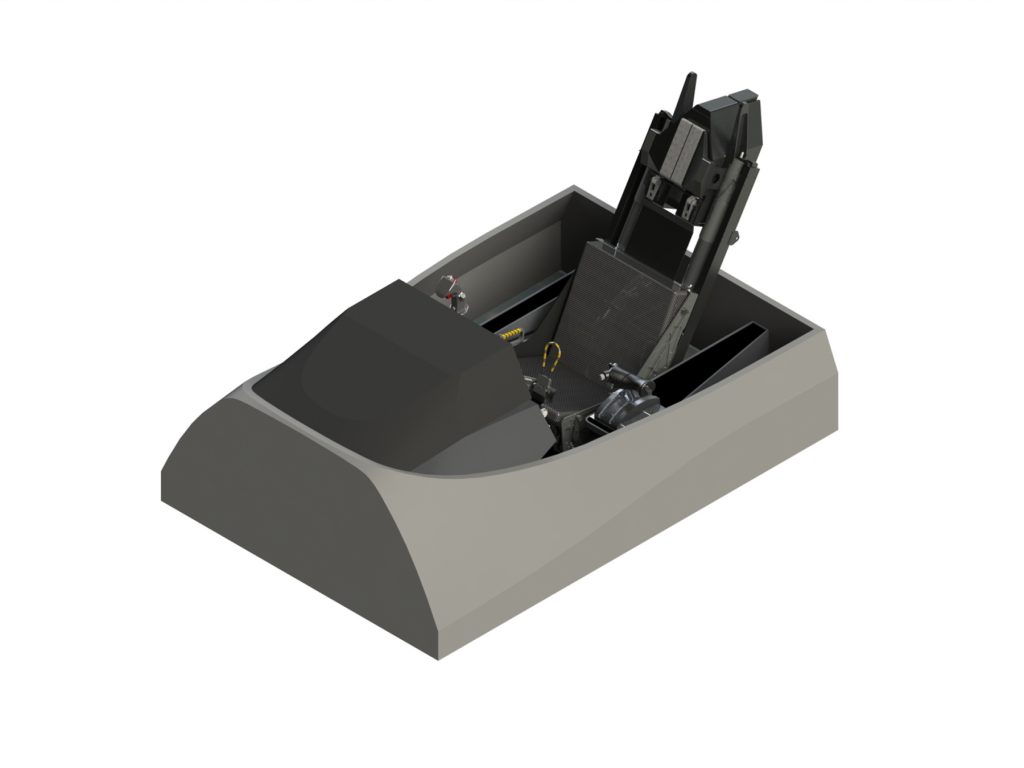
All piloted SM-39s will be equipped with a cockpit module that will serve as a self-contained, A-10 inspired armored “bath tub” structure to ensure crew protection and survivability. Designed for high altitude operations up to 125,000 ft, the cockpit will provide both armor protection and a degree of radiation shielding through the use of titanium foam metal and titanium diboride foam metal sandwich construction. Cockpits will be equipped with next generation Martin Baker zero-zero ejection seats or Advanced Concept Ejection Seats/crew escape capsules as produced by a Stavatti ITM. For design purposes, the baseline ejection seat is the Martin Baker MK18 or Collins ACES 5. Employing many lessons learned from the F-16, seats will be mounted at a recline angle to enhance pilot g-tolerance. The SM-39 cockpit will be configured and arranged in a manner similar to other Stavatti aircraft cockpits allowing a rapid transition between Stavatti aircraft types. The cockpit is generally similar to the SM-27 in layout and will be largely identical to the SM-36 cockpit, with exception that provisions are made for the SM-39s twin engines and forward internal weapons bay. The cockpit will be equipped with a proven Carlton OBOGS for aircrew oxygen generation. Piloted aircraft will be produced in both single seat (SM-39S) and two seat tandem (SM-39T) variants.
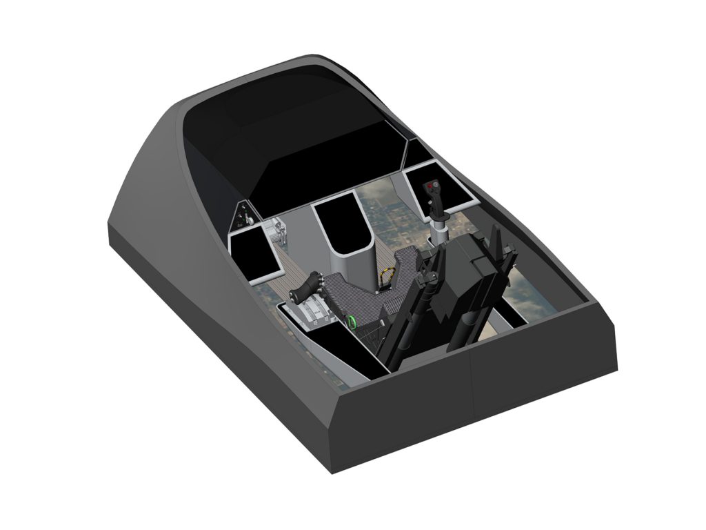
SM-39s will feature an all-glass cockpits benefiting from light-weight, thin-sheet wide-area color LCD technology. Large Area Active Display (LAAD) MFDs will be employed with the LAAD being a MOTS option. Holographic Projection Displays (HPDs) for moving map and aircraft situational awareness display may be incorporated into the aircraft depending upon their technical maturity. Cockpits will feature HOTAS flight controls with a F-16 style flight control and throttle grip and rudder pedals. The SM-39 will feature a Canopy Embedded Display (CED) whereby the HUD information is projected directly onto the aircraft canopy providing a 330° targeting and situational awareness information.
The SM-39 cockpit will be equipped with a single-piece clamshell bubble canopy. The canopy will provide F-16 and F-22 levels of visibility for comparable pilot situational awareness. The canopy will be iridium coated for RCS reduction and will safely sustain the impact of a 4 lb bird at 550 kts. Engineered for sustained high speed flight (Mach 4+) operations, the canopy transparency is composed of ultra-lightweight supermicrocellular foams processed from biphenyl end-capped poly (acrylene ether) polymers as developed by Wrightmat, or canopies produced by Stavatti using high temperature polymers developed under a license based on Hill U.S. Patent 5,670,574.
All SM-39 Cockpits benefit from a HOTAS flight controls arrangement consisting of a right hand/starboard mounted Flight Control Grip (F-16 derivative) right console mounted flight control column, full deflection rudder pedals, dual power control levers (F-16 grip inspired). Flight and throttle grips are provided by Esterline/Mason Electric and are based upon current production articles for the F-16 to reduce tooling complexity. HOTAS provides toggles for aircraft wing flaps, speedbrake, trim, sensors, weapons release, microphone, etc. Rudder pedals are fully adjustable. Dual flight controls are provided in two-seat variants.
All flight controls, displays, instruments, system controls and circuit breakers are accessible from both forward and aft crewstations by crew members with crew seat restraints fastened. SM-39 cockpits will feature new design Stavatti proprietary display systems including a Canopy Embedded Display and Stavatti touch screen Active Displays (AD). Developing innovative cockpit systems, the SM-39 will serve as the new Stavatti standard for an integrated cockpit that provides a high degree of situational awareness.
The SM-39 cockpit will combine the Canopy Embedded Display and Stavatti Active Displays with a unique open cockpit that features twin flight control grip pedestals, a display panel pedestals, rudder pedals and a large area Situational Awareness Display system whereby the cockpit floor as well as right and left cockpit side panels serve as displays on which to project the aircraft’s visual surroundings with optional IR, Night Vision, UV, SAR and moving map imagery.
Projecting optical and sensor imagery that is provided through the aircraft’s optical, Doppler radar and FLIR sensor suite, the floor and side-wall mounted cockpit Situational Awareness Display (SAD) combined with the aircraft’s Canopy Embedded Display (CED) immerses the pilot in a sensory network that emulates a near perfect view of the world around the aircraft. Combined with anticipated holographic projection (circa 2025), the SM-39 cockpit will provide a monumental leap in situational awareness. Eliminating traditional right and left control consoles, flight and throttle grip mounting pedestals will incorporate multi-functional touch screen controls to access traditional right and left cockpit console control interfaces.
The aircraft may also benefit from novel control interfaces including touch-screen interfaces and illuminated smart LED push-button switches to replace traditional toggle switches. These switches provide full force feedback and illuminated acknowledgment while also incorporating safety features to prevent inadvertent activation. In so doing the SM-39 may be configured to feature conventional control panels and interfaces for specific avionic systems and LRUs, or benefit from an integrated cockpit conceived for interface with multi-mode, dynamic software driven avionics, electromechanical actuators, electric jet systems and even an autonomous, artificially intelligent workspace and warfighter environment.
The Canopy Embedded Display (CED) is a new Head Up Display (HUD) technology that replaces conventional aircraft HUDs as well as Helmet Mounted Displays (HMDs), serving as the aircraft’s primary visual flight reference display. The Stavatti CED benefits from pioneering consumer electronics research in the field of transparent, curved LED displays, including Organic Light Emitting Diodes (OLEDs). Applying this technology to aircraft canopies under license from a specific industry partner, the inside of the canopy is layered with a transparent thin film LED which then projects data and symbology directly on the canopy interior which in turn, serves as the aircraft’s HUD.
Presenting active visual situational awareness, the CED allows the aircraft’s canopy to serve as a large, wrap-around, transparent display suitable for displaying both menus and HUD symbology as generated by the aircraft’s multi-function display processors. The CED provides visual cuing locations for radar and sensor targets that are yet visually out-of-range while providing both situational awareness and heading cuing for navigational purposes.
Also enabling the dimming and blacking-out of the canopy, the CED mitigates solar glare effects, reduces cabin temperature and can provide microsecond dimming to protect pilot vision during nuclear blasts.
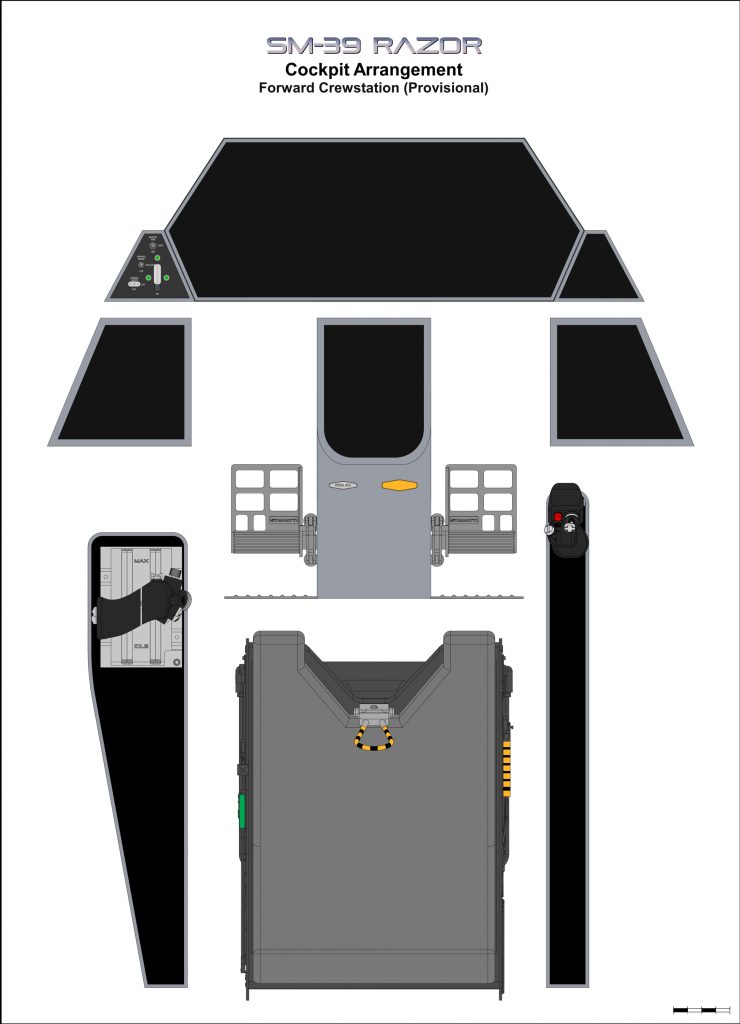
Stavatti touch screen Active Displays (AD) are next generation lightweight LED Multi-Functional Displays of unique trapezoidal configuration. A ruggedized display system engineered to MIL SPEC for operation in extreme environments and under high accelerations, this display technology allows for the production of non-rectangular, large format, cost competitive displays for both military and civil aircraft. Enabling next generation, all glass cockpits, Stavatti’s Active Displays will be produced by a leading military and consumer electronics industry team member for exclusive use in future Stavatti cockpits. Standard Display sizes for the SM-39 include a 29 x 11 in primary display, a 7 x 9.3 in center display and twin 7.2 x 8 in secondary displays to the right and left of the center display. All Stavatti display technology will feature proprietary, internally developed symbology and software developed and produced under contract for Stavatti by a qualified industry team member.
Benefiting directly from the technology and talent of Silicon Valley and the Dulles Tech Corridor, Stavatti’s strategic partnerships will enable the creation of displays, symbology and secure encrypted driver software unique to the industry.
All SM-39 cockpits will be IFR certified and designed for Generation III night vision compliance and Helmet Mounted Cuing Systems/ Integrated Helmet and Display Sighting Systems (HMCS/IHDSS). Display panels are complemented by a comprehensive warning annunciator system, integrated environmental control vents and standby control interfaces. The SM-39 Razor follows the standard Stavatti military aircraft cockpit configuration allowing rapid transition between Stavatti fighter, attack and trainer aircraft.
Structure & Materials
The SM-39 will be a metal aircraft benefiting from a variety of advanced alloys and construction techniques. Enabling high speed flight with high strength-to-weight ratios, the SM-39 will have proprietary non-carbothermic titanium diboride cermet skins. These skins will serve as the exterior face sheet for a closed cell foam metal sandwich structure that has a titanium foam metal core for high temperature applications or an aluminum foam core in lower temperature regions. Benefiting from foam metal sandwich structures throughout, the SM-39 is a semi-monocoque aircraft in which a metal sandwich skin is supported by an internal structure of bulheads, frames, spars and ribs made from high performance titanium and aluminum lithium alloys. Employing a minimal number of rivets or screw fasteners, the SM-39 is built from sandwich skins that are welded to titanium bulkheads, frames, spars and ribs using laser or Friction Stir Welding (FSW) techniques. Designed for high temperature operations, the combination of titanium diboride cermet skins with foam metal sandwich structures allows airspeeds in excess of Mach 4.5.
Resulting from nearly three decades of advanced research that has resulted in a manufacturing process that will yield nearly pure (99.99%) titanium diboride metal ceramics, Non-carbothermic titanium diboride is an advanced proprietary Stavatti material that offers tremendous benefits over existing metal and ceramic technologies. Key material characteristics include a High Hardness (36 GPa, 3,400 Knoop), Low Friction (0.2 Friction Coefficient @ 1100K), High Elasticity (813 Gpa), Extreme Temperature Resistance (Melting Point ~ 3500 K), low density (4.13 g/cm3 @ 99% density, <2.00 g/cm3 in hybrid foam), High Electrical Conductivity, Ease of Machinability and the Ability to be RF/Induction welded.
This ceramic metal (cermet) material will be used throughout the SM-39 with applications including external fuselage, wing and tail skins, high temperature air inlet duct, high temperature internal bulkheads and frames, bearings and most critically, high temperature E1400 engine components including the compressor face, the combustion chamber, the turbine, afterburner duct and exhaust nozzle.

Produced and DoD qualified by Stavatti, this material will be unique to the SM-39 Razor and other high performance Stavatti combat aircraft. The sandwich construction results in a structure that offers high degree of sound and vibration dampening as well as high impact resistance, fatigue cycle tolerance and superior survivability. Moreover, the closed cell foam structure is conducive to a smooth, low-drag skin-surface that can be produced quickly at a low cost and lower parts count. A new material manufactured by proven and qualified by companies including Fraunhaufer IWU of Chemnitz, Germany, today there are many qualified manufacturers that are producing foam metal sandwich structures for aerospace, defense, automotive, and other applications. Stavatti will be building upon these successes to standardize and qualify a proprietary approach toward the production of foam metal sandwich structures for FAA certified and DoD qualified aircraft.
The foam metal sandwich approach will feature skins which are 0.032 to 0.25 in thick separated by a low density foamed metal core measuring as thin as 0.5 to 1.0 in to thicknesses over 9 in for full depth wing structures. The foamed metal core is metallurgically bonded to the metal face sheets on a molecular level. This metallurgical bonding is the result of the in-situ bonded proprietary manufacturing approach whereby the core is foamed between solid face sheets, allowing the foam to fuse and form a molecular bond. The face sheets will use 100% density material while the lower density foam core will have a range of material density from 3% to 10% with an average density of 8%, depending on specific airframe structural component.
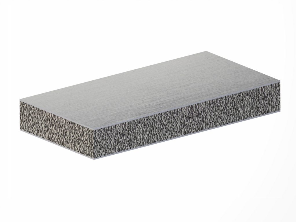
The closed cell metal foam sandwich structure has an excellent stiffness-to-weight ratio, a greater strength-to-weight ratio than traditional construction and lower thermal conductivity with a high degree of fire resistance. The sandwich construction results in a structure with a high degree of sound and vibration dampening while offering high impact resistance, fatigue cycle tolerance and superior survivability. Moreover, the closed cell foam structure is conducive to a smooth, low-drag skin-surface that can be produced quickly with a significantly lower parts count at less cost.
A new material manufactured proven and qualified by companies including Fraunhaufer IWU of Chemnitz, Germany there are many companies that are currently producing foam metal sandwich structures for a variety of aerospace, defense, automotive, machine and other applications. Implementing the foam metal sandwich structural approach, the SM-39 fuselage will consist of independently manufactured modules that are bolted together to form a completed fuselage structure.
Each module features a foamed metal sandwich skin consisting of titanium or titanium diboride cermets that are welded to a titanium foam metal core. Total sandwich thickness will measure approximately 1.0 in thick, although sandwich thickness may vary based upon structural requirements. The fuselage sandwich skins are then welded to an internal substructure consisting of machined or built-up laser welded bulkheads, frames and longerons. The Aircraft wings and empennage will be composed of titanium and titanium diboride cermet skins that are separated by a welded titanium foam metal core. The wing structure is reinforced with full-depth titanium sinewave spars. A limited number of titanium sinewave ribs will also be incorporated into the wings to serve as a structural reinforcement at wing hardpoint locations.
Sheet sandwich structures will be formed to contour shapes using laserforming techniques, explosive stimulated hydraulic welding or similar method of precision shaping. Other components may be formed prior to creation of sandwich structure wherein molten metal is injected into the sandwich facesheets whereafter the motel metal is foamed and cooled to result in a molecularly bonded, foam metal sandwich part. Low radius of curvature parts, including wing and tail skins will likely be stretch formed or stretch formed using laser assistance and then welded to a laser formed foam sandwich.
Thick wing and tail structures may be machined from sheetstock to a desired thickness and machined configuration. Aircraft landing gear may also benefit from titanium foam metal construction to reduce component weight. While specific airframe hardware and components may consist of milled aluminum, titanium and stainless steel, most of the external aircraft surface area will consist of titanium foam metal sandwich structure.

The foam metal sandwich structural technology has been utilized in the aerospace industry for many decades for non-structural applications, including filtration. Although not yet applied as a structural element for airframe structures, Stavatti perceives this technology as a break-through that not only increases aircraft structural integrity but allows significant reductions in airframe fabrication time and cost. Significantly reducing the cost of titanium components this technology will enable the production of all metal aircraft which significantly eclipse any benefit from the use of fiber composites or other materials. Already engaging with the Air Force Research Laboratories regarding foam metal sandwich structures, Stavatti will certify and qualify both titanium diboride cermet and titanium foam metal sandwich structures for military aircraft applications as part of the comprehensive SM-39 military qualification process.
A direct substitute for honeycomb metal sandwich, to reduce development costs, SM-39 demonstrator aircraft SM-39s could feature a laser welded titanium honeycomb core to which titanium or titanium diboride cermat facesheets are welded or diffusion bonded. These titanium sandwich panels could be used as direct substitutes to foam metal sandwich panels with characteristics that have been well demonstrated. While production aircraft will feature foam metal cores, use of titanium honeycomb cores in prototype aircraft will expedite the development program. Due to their omnidirectinal-uniform strength superior impact resistance, survivability and their possible use as pressurized fuel tanks, foam metal structures are the desired core material for the SM-39 in any case.
Approximately 95% of the aircraft will be metal with 5% being composites and other materials. High temperature composites will be used in all bandpass fairings including the radome and conformal antennas. The high temperature composites will employ high temperature resins, such as NASA Langley RP46, which can operate for over 10,000 hours at temperatures in excess of 700° F. A new proprietary high temperature resin capable of sustained temperatures in excess of 3,000° F designed specifically for the aerospace industry may also be used.
This resin, as defined in Hill Patent 5,670,574 has been licensed by Stavatti for production and use in a variety of applications, including the bandpass radome and antenna fairings of high performance, high speed aircraft. The fiber materials used in SM-39 composites include Hexcel IM9 graphite composite fiber, high performance Basalt filament and woven fiber, Boron and Borene, and a mission specific band pass aramid for use in SM-39 radomes and antenna fairings.
The SM-39 structure will be designed for a 20,000-hour service life at an annual usage of 350 flight hours for a total lifetime of over 57 years. The maximum limit load factor is +7.5-g and -3.75-g at a Maximum Takeoff Weight (MTOW) of 100,500 lbs. The maximum limit load factor at USN carrier Gross Takeoff Weight of 85,500 lbs is +8.8-g and -4.4-g. The maximum limit load factor in the Clean Takeoff weight configuration of 75,500 lbs is +10.0-g and -5.0-g. The maximum limit load factor at Design Takeoff Weight is is +9.6-g and -4.8-g. For all gross weights, the Ultimate load factor is 1.5 times limit load factors.
Fuselage
The SM-39 fuselage is a semi monocoque titanium foam metal sandwich structure composed of two primary modules: a nose module and the mid fuselage. The nose module includes the radome, forward nose, cockpit module and forward weapons bay. The mid fuselage is the core airframe structure incorporating the engine nacelles, air intakes, landing gear bays and mid weapons bay. Both modules are constructed as stand-alone structures which are bolted together allowing a variety of nose modules, including two seat tandem configurations, to be mated to the mid fuselage interchangably. Both modules feature titanium foam metal sandwich skins with non-carbothermic titanium diboride cermet face sheets with a total thickness of approximately 1.0 in. These skins are supported by an internal structure of machined and built-up titanium and aluminum-lithium bulkheads, frames and longerons. Skins and internal structural members are laser or friction stir welded throughout. All fuselage contained systems, including avionics, electrical, armament hydraulic and the cockpit module, are secured with vibration damping fasteners or quick release/quick remove mounting trays to integrated alloy mounts. The fuselage interior is arranged to ensure that TEMPEST sensitive avionic and electrical systems are contained within a Faraday cage. The fuselage is equipped with a retractable boarding ladder as well as support and maintenance hatches.
Wings
The SM-39 wings are of low aspect ratio, mid-wing, cantilever type with a trapezoidal planform. Wing leading edge sweep is 50° and trailing edge sweep is 50°. Sweep at the 25% chord is 50°. Wing span from tip to tip is 54 ft 6 in. For carrier suitability the wings may fold, reducing overall span to 32 ft 0 in. Gross wing area is approximately 1,132 sq ft of which roughly 53% is blended into the fuselage as buried wing area. Wing aspect ratio is 2.62. The wing mean root airfoil is a proprietary Stavatti 4% thick airfoil similar to the NACA 62A204. The mean wing tip airfoil is a proprietary Stavatti 4% thick airfoil. Wing incidence is 0°. Wing dihedral is 0°.
The wing is equipped with full span leading edge flaps that can be deflected 5° up and 35° down. The trailing edge of the wing is equipped with inboard double slotted flaps with a maximum deflection of 40°. The trailing edge flaps are broken into inboard and outboard segments. The outboard flaps function as plain flapperons at speeds below 450 Knots to improve roll performance. The wing is also equipped with spoilers for directed lift force control. To improve low speed handling and reduce aircraft stall, approach and landing speeds, the SM-39 is equipped with a blown flap boundary layer control system. This blown flap system draws from engine bleed air and can be used in takeoff, maneuvering and landing. The wing has a titanium foam metal sandwich structure consisting of a non-carbothermic titanium diboride cermet skin supported internally by eight titanium sine wave spars and titanium foam metal. The wing incorporates discrete titanium foam metal fuel cells and has provisions for two external hardpoints per wing. Each wing hardpoint will be rated to 4,500 lbs at 7.5-g.
Leading Edge Wing Strakes
The SM-39 features two prominent leading edge root extensions/strakes (“wing strakes” or “strakes”) that project as trapezoidal structures immediately ahead of the wing root and to the right and left of the fuselage, separated from the fuselage by an air gap. Beginning with a pointed tip at the nose of the aircraft, at supersonic speeds, the tip of each wing strake forms a shock wave, the angle of which is dependent upon flight Mach number.
Each strake is engineered such that the shock wave remains outside both the aircraft’s wing and tail at speeds up to Mach 3.0, allowing reduced wing and tail wave drag at speeds up to Mach 3.0. At speeds up to Mach 4.0, only 9.5% of the aircraft’s wing area is outside of the shock cone while the empennage remains entirely within the shock cone. In so doing, each wing strake is a wing shock wave management and aircraft drag reduction mechanism. Each strake is composed of a non-carbothermic titanium diboride cermet skinned, titanium foam metal sandwich structure approximately 1.0 in thick. This structure is supported by titanium and aluminum-lithium bulkheads and frames. Each strake serves to prove vortex generated wing flow enhancement at high AoA as well as to ensure continuous air intake airflow at high AoA. Each wing strake is equipped with an in-flight refueling interface with a USAF UASSRI interface located on the left strake and a USN style retractable refueling probe located on the right strake.
Empennage
The SM-39 empennage consists of independent horizontal stabilizers responsible for pitch, roll and yaw control. To reduce aircraft RCS and visual signature the SM-39 does not feature fixed vertical stabilizers. The SM-39 horizontal stabilizers are of low aspect ratio cantilever type with a sawtooth trapezoidal planform. The horizontal stablizer is an all-moving tail that can provide pitch and roll control. Single all moving slabs, the new design empennage is equipped with trailing edge decellerons for yaw control. As featured in many Northrop aircraft including the P-61 and F-89, the tail of the SM-39 will use differentially actuated decellerons mounted on the horizontal tail for yaw control. A novel feature, the SM-39 will be the first aircraft to have decellerons mounted on a horizontal tail. The decellerons operate in conjunction with powerplant thrust vectoring and yaw enhancement through powerplant differential thrust vectoring.
Each horizontal stabilizer has an area of approximately 170 sq ft for a combined total aircraft horizontal stabilizer area of 340 sq ft. Individual stabilizer aspect ratio is 1.54. Of novel planform, aircraft horizontal stabilizers enhance aircraft low observability features and are planform aligned with sawtooth leading and trailing edges set at 50°. Tail root airfoil is a proprietary 4% thick wedge airfoil section with thickness that varies with span, providing constant taper. The tail incorporates a novel training edge decelleron. The horizontal stabilizer features titanium sine-wave spars, titanium ribs and titanium external skins. Benefiting from a full depth sandwich structure, the external skins are welded to a titanium foam metal core. To reduce the possibility of pitch up and to ensure planform alignment for RCS reduction, the tail is situated at the same level as the trailing edge of the main wing. Extremely close coupled there is a maximum 2 inch gap between the wing trailing edge and horizontal stabilizer leading edge. The Horizontal tail has fixed dihedral at 0° and is designed to pivot up and down 30°.
The all-moving horizontal tails with trailing edge decellerons was adapted in 2016 with the redesign of the SM-39. Initial variants of the SM-39 featured a variable dihedral empennage design that would allow the SM-39 to reconfigure its tail to address flight and mission demands. This tail design consisted of four individual units with two tails on the port and starboard of the aircraft. These tails would be mounted to the aft fuselage using individual pivot trunnions to the aircraft aft fuselage. The trunnions were of variable pitch type and are electromechanical actuated. The tail would benefit from variable dihedral as inspired by Raymer Patent 4,354,646. The variable dihedral tail units allow a maximum of 90° dihedral on the upper tail units and a minimum of 45° anhedral on the lower tail units. Tail dihedral would be optimized for takeoff, cruise, maneuver and landing settings by the the aircraft’s flight control system. For a stealthy supercruise, the two tails merge to their zero dihedral condition, enabling the wing and tail to function as a compound delta with a favorable volume distribution for low wave drag. With reduced observability, the SM-39 would function as a tail-less aircraft at zero dihedral. For maneuvering, the tail would vary to serve as a combination of V, Y and conventional L tails, ultimately allowing the SM-39 to realize nearly the same tail volume coefficients as an F-15. For takeoff and landing when the pitching moment of double slotted flaps must be relieved, the tail may be set to an L or other combination that results in maximum projected horizontal stabilizer area.
Each tail unit would be a two piece structure that serves as an all-moving stabilator designed to pivot up and down 25°. Equipped with all moving leading and trailing edge flaps, the leading and trailing edge of each tail could be configured to allow the efficient blending of upper and lower tail surfaces when they close to within 0.5 inches in the zero dihedral condition. When not closed, the variable leading and trailing edges serve as high lift and flight control devices, as well as trailing edge trim tabs. Each individual tail unit is composed of a titanium foam metal sandwich structure with multiple titanium spars. Tail leading edge sweep is 52.6° and trailing edge sweep is 38.3°. Sweep at the 25% chord is 40.75°. Tail unit span from tip to root is 10.07 ft. Each individual tail has an reference area of 99.2 sq ft and a corresponding aspect ratio of 1.02. Each of the four tail units have a 2% thick Stavatti symmetrical wedge airfoil at the root, allowing for the effective creation of a 4% wedge airfoil section in the closed, zero dihedral condition.
While this split design, variable dihedral empennage configuration would provide many aerodynamic and control advantages, its overall complexity resulted it being replaced by the single slab non-variable dihedral all moving horizontal stabilizer with trailing edge decellerons for yaw control. Due to the advantages of a split empennage system, the concept continues to be explored as a possible solution for SM-39 aerodynamic stability and control. For the purpose of this document, the SM-39 configuration SM39-1006-011 is equipped with all moving horizontal stabilizers with integrated decellerons.
Flight Controls
The SM-39 primary flight control surfaces consisting of ailerons, flapperons, double slotted flaps, leading edge flaps, spoilers, all-moving horizontal stabilizers and decellerons configured for reduced signature. Wings are equipped with Boundary Layer Blowing and Circulation Control for maneuvering and lift enhancement at low speeds. The aircraft is also equipped with a fuselage mounted speedbrake and 2-D thrust vectoring with thrust reverse for enhanced pitch and roll control. Yaw control is enhanced through judicious application of powerplant differential thrust. The aircraft may also be equipped with low-signature pitch yaw balanced beam thrust vectoring for enhanced pitch, yaw and roll. To enhance wing performance, Stavatti is studying the possible application of variable camber, mutable wings which employ wing warping and flexing for roll control as a successor to conventional ailerons, slats and flaps.

Stavatti is developing a proprietary Variable Camber/Variable Thickness (VC/TC) mutable wing which allows both a change in wing chord camber, as well as the ability to vary wing thickness-to-chord ratio by as much as 5%. VC/TC will allow a 4% thick wing to translate to 9% thickness, thus significantly altering overall airfoil performance characteristics. This mutable wing technology does not vary aircraft planform, but alters thickness, camber, incidence and dihedral angle while allowing the use of wing warping and local wing section thickness to induce aircraft roll control and chordwise load distribution. Mutable wing or VC/TC wing equipped aircraft will feature proprietary slotted flap and slat configurations that blend appropriately into the individual wing configuration. Coupled with Variable Camber mutable wings, The SM-39 may also incorporate features that allow it to benefit from Directed Lift Force Control (DLFC) as demonstrated in the F-16 CCV/AFTI. The DLFC technology will enable the SM-39 to execute uncoordinated flight maneuvering for tactical advantage.
The SM-39 flight control system will be a four channel, full-authority, Digital Power-By-Wire (PBW) system as provided by Industry Team Partners (ITMs). This flight control system will be used in the SM-39 and will interface directly with any unpiloted aircraft flight control and guidance systems. All flight controls will be of electromechanical type that may be produced by ITMs or designed and produced by Stavatti.
Fuel System
The aircraft fuel system is composed of rigid fuselage, strake and wing fuel tanks.
The maximum internal fuel load is 4,621 US Gallons equivalent to 30,037 lbs of JP-4 or 30,961 lbs of JP-8 at standard conditions. SM-36 fuel tanks are sized for a maximum capacity of 4,621 gallons of JP-8, plus any volume necessary for fuel tank self-sealing features. Unusable internal fuel is approximately 961 lbs. Design SM-39 maximum internal fuel load (useable fuel) is 30,000 lbs. For increased survivability the fuel tanks are nitrogen pressurized with a Cobham NC1029 OBIGGS.
Fuselage and strake fuel tanks are of rigid, laser-welded titanium type fitted lined with open cell reticulated foam as secondary survivability protection in addition to the OBIGGS. Standard SM-39 wings feature a full-depth foam metal sandwich structure of open cell titanium foam metal type to serve as both a structural core as well as a sealed fuel cell. All fuel tanks are pressurized with fuel volume being dynamically controlled and shifted between fuel cells during flight for enhanced aircraft Center-of-Gravity management. Approximately 35% of the aircraft’s fuel is stored within strakes while 58% is carried in the fuselage with 7% carried within the aircraft’s wings. A fuel quantities and tank arrangement diagram is provided:
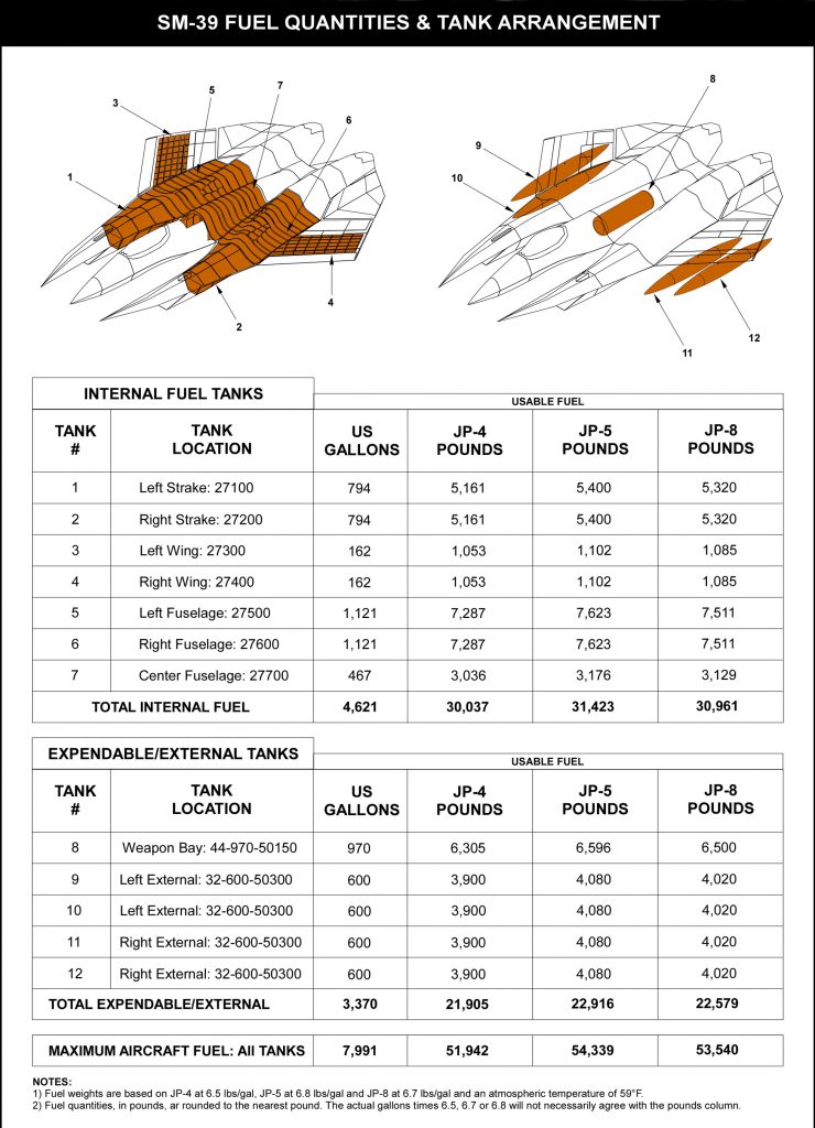
Ground refueling may be accomplished through a single point refueling interface is located on the port lower fuselage, while gravity refueling may be accomplished through a single fuselage fueling point. For in-flight refueling, the SM-39 will be equipped with a Universal Aerial Refueling Receptacle Slipaway Installation (UARRSI) to enable flying-boom style refueling as well as retractable in-flight refueling probe to facilitate probe-and-drogue style refueling. The UARRSI is dorsally located on the left wing strake while the probe-and drogue in-flight refueling system is located dorsally located on the right wing strake. To extend aircraft range four wing hardpoints are plumbed for external fuel tanks. The SM-39 may carry up to four Cobham external fuel tanks with a maximum capacity of 600 USG per tank for a total of 2,400 USG. A custom 970 USG tank may also be carried within the main internal weapons bay for ferry flights.
Aircraft Systems
The SM-39 will be an “Electric Jet” employing all-electric subsystems including flight controls, spoiler and speedbrake actuation, air inlet shock ramp actuation, canopy actuation, landing gear retraction, wheel brake actuation, weapon system firing and all other systems which are traditionally hydraulic or pneumatic in nature. The SM-39 flight control system is a full-authority, Digital Power-By-Wire (PBW) flight control system. The PBW system features self-contained electrohydrostatic primary flight control actuators (EHAs), electromechanical actuators (EMAs) and electrically driven power drive units (PDUs). With a PBW flight control system that drives electric flight control surface actuators, this all-electric aircraft will have reduced overall airframe weight, quicker system response time and dramatically reduced MTBF.
The SM-39 flight control system is a full-authority, Digital Power-By-Wire (PBW) flight control system. The PBW system features self-contained electrohydrostatic primary flight control actuators (EHAs), electromechanical actuators (EMAs) and electrically driven power drive units (PDUs). EHAs and EMAs are developed and produced by leading industry team members including Moog, Parker Aerospace and Beaver Aerospace. EHAs and EMAs position and actuate the aircraft’s flapperons, double slotted flaps, leading edge flaps, spoilers, all-moving horizontal stabilizers and decellerons, canopy, air stair, landing gear, landing gear doors, in-flight refueling doors, in-flight refueling probe, speedbrake, the 20mm cannon system and internal weapons bay doors. Additional aircraft mechanical components that require dynamic linear or rotational actuation will likely be electrically driven by EHAs, EMAs and PDUs.
SM-39 EHAs enable flight control and systems actuation without the need for a central hydraulic system resulting in reduced aircraft weight, more efficient power consumption and improved aircraft maintainability. The EHAs consist of integral fixed displacement reversible high speed pumps driven by brushless electric motors. The EHAs are dual tandem designs with simplex hydraulic output that incorporate both fail-safe features and overload protection. The EHAs have operating pressures up to 5,000 psi with an electrical output range of 270 Vdc or 115 VAC with a transformer rectifier. SM-39 EMAs include both linear and rotary electromechanical actuators that utilize a ball or Acme screw.
The EMA screws are driven by brushless electric motors through a torque sum gear train. The EMAs may have a skewed roller or a fail-safe electromechanical brake. Linear or rotary variable differential transformers determine position of flight control surfaces actuated by the EMA.
In the event of primary load path failure, the EMA’s primary load path is locked in place and load is transferred to a secondary load path. This enables continued operation of aircraft primary flight control surfaces during failure.
The PBW system is quad-redundant, features BIT and benefits from flight control laws that enable variable stability and provide the pilot with maximum flight control authority enabling the aircraft to be fully aerobatic. PBW flight control law software allows the aircraft to perform all standard maneuvers including the stall, slip and spin, enabling full expression of exercises throughout any advanced training syllabus. The PBW architecture interfaces directly with pilotless remote piloted and autonomous flight command systems. Ailerons, flapperons, and all-moving horizontal stabilizers are internally mass balanced. Flight control surfaces may be deflected in concert or independently to enable unique flight control deflections and resulting aircraft maneuvers as controlled by the aircraft flight control system. Flight crews may pre-program specific maneuvers for precision execution by the aircraft flight control system.
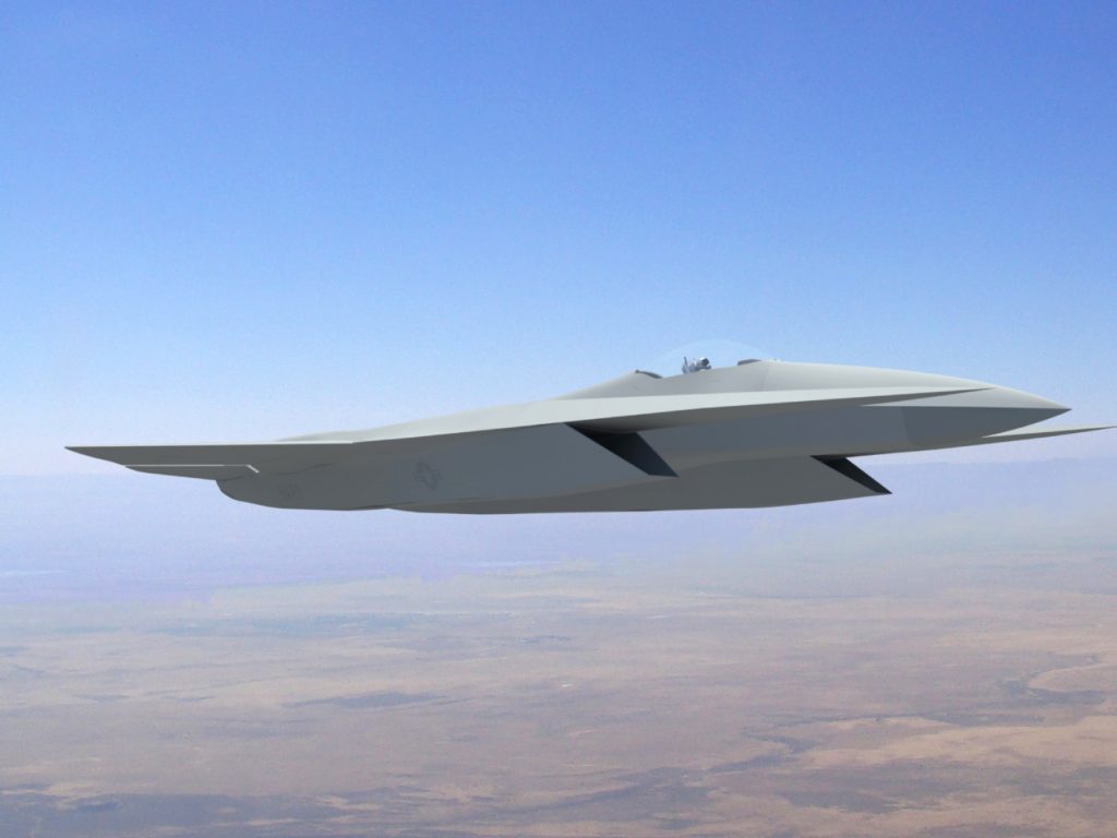
The SM-39 features two independent 4,000 psi (276 bar) hydraulic systems driven by electrically driven pump. Hydraulic systems are interconnected to assure reduncy. Hydraulic systems actuate, landing gear normal braking, and nose wheel steering and limited additional systems. Hydraulic pressure is maintained automatically and is suitable for aerobatics and inverted flight. The SM-39 electrical system supplies 115 volt, three-phase, 400 cycle AC power and 28 VDC per MIL-STD-704D. Four independent sources are used for power generation including an engine driven primary switched-reluctance starter and generator, a Honeywell G230 APU, a RAM air turbine and two high performance sealed-cell or lithium silicon graphene batteries.
AC power is supplied by two static inverters. Power is normally supplied by one inverter with the second serving as a backup. DC power is supplied by one 24 VDC battery. The starter/generator is a combination engine starter and 28 VDC generator.
The secondary generator is a 28 VDC generator. The powerplant features an APU to supply DC and 400 Hz power, bleed air/air conditioning and hydraulic pressure. An external 28 VDC ground power connector is provided.
To provide multi-megawatt on-board energy to power a variety of aircraft subsystems including sensors, directed energy weapons, electromagnetic pulse devices, MHD propulsion systems, and active wave attenuation systems, the SM-39 may be equipped with engine driven, oil-cooled high speed, multi-megawatt synchronous generators [8]. Pioneered by Electrodynamics Associates, Inc [9]., as sponsored by a USAF SBIR initiative to provide energy for an aircraft mounted directed energy weapon, each generator for the Stavatti application will develop a maximum of 1.5 MW using a 15,000 RPM salient-pole, wound-rotor synchronous generator with a rotor embedded exciter and oil cooled rotor and stator. Featuring an aluminum lithium housing for reduced weight, each generator will operate at 1,500 Hz and will have an approximate weight of 180 lbs.
The Aircraft is equipped with Cobham OC1132 OBOGS and a NC1029 OBIGGS. The cockpit is pressurized, air conditioned and heated. The aircraft will feature an Electro-Expulsive De-icing System (EEDS) as developed by NASA and produced by IMS-ESS. EEDS is used for wing and horizontal stabilizer deicing. Electric deicing is used in the pitot tube, static ports, AoA transmitter, stall warning sensor and air intakes. Powerplant bleed air deicing is provided for the canopy and engine inlet. A fire detection and suppression system is provided for the engine, avionics bay and cannon/ammunition bay.
Landing Gear
The SM-39 will have electromechanically retractable, tricycle landing gear. The aircraft will have a wheel base of 28 ft 4 in and a wheel track of 16 ft 9 in. Each landing gear unit will have oleo-pneumatic shock absorbers and hydraulically actuated carbon disk brakes with anti-skid. The gear is designed for a maximum vertical descent rate of 20 ft/s and a 5-g gear load factor. Gear design retraction and extension speed is 6 seconds. The gear is designed to support a Maximum Takeoff Weight (MTOW) of 109,000 lbs.
The nose gear is a steerable twin wheel forward retracting unit. Retraction will be achieved by a single electromechanical actuator attached to the right side of the strut that serves as a self-locking brace. The nose gear rotates 101 degrees up into the nose wheel well. A single strut unit, 77.6% of the nose gear will be constructed from Ferrium S53 while 14.5% will be built from Ti-6Al-4V Titanium. The nose wheel has dual Goodyear 22 x 6.6-10 20 ply ribbed tires. These are the same size tires used in the F-14 and F/A-18 nose wheels and have a maximum pressure of 270 psi and a maximum speed rating of 281 mph.
The SM-39 main landing gear consists of fuselage air intake duct mounted, single strut, oleo-pneumatic single wheel units with anti-skid carbon disk brakes. The main gear strut retracts 108 degrees forward with main gear pivot trunions being mounted to main bulkheads with an axis of rotation tilted to enable rotation of the main wheel 90 degrees, allowing it to lay horizontal within the wheel well. To reduce storage space, the landing gear telescopes upon retraction. The gear is retracted and extended by a single electromechanical actuator which serves as a gear lock-down support brace when extended. In the event of actuator failure, the gear is designed to deploy by gravity into a locked down position. The main gear struts are of conventional oleo-pneumatic type with a fixed orifice metering device. Rght and left gear struts are identical in type. The struts are composed of integrally machined and built up Ferrium S53 and Ti-6Al-4V components. Approximately 65.6% of the main gear is composed of Ferrium S53 while 16% is Ti-6Al-4V.
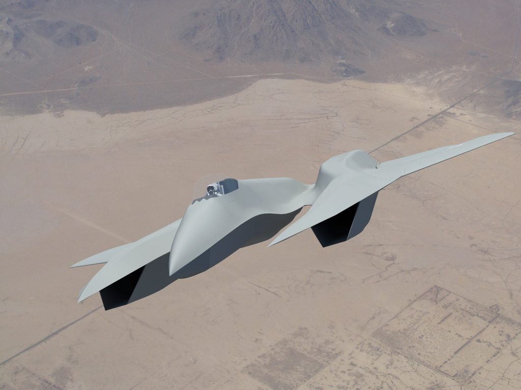
The remainder of the main gear is non-metal materials including the main tires. The main gear has a stroke of 22.5 in with a static compressed stroke of 7.5 in. Each main gear strut features a single Stavatti produced Ti-6Al-4V wheel with a Goodyear 44.5 x 16.5-20 30 ply Flight Leader tire with a maximum pressure of 195 psi and a maximum speed rating of 225 mph. The main wheels will be fitted with hydraulically actuated carbon disk brakes.
Low Observability & Signature Reduction
The SM-39 will feature technologies to significantly reduce Radar Cross Section (RCS), infrared signature, electromagnetic signature, visual signature and aural signature. Of these five signatures, reduction of RCS is the primary focus of SM-39 observables management.
To reduce SM-39 RCS, four principal approaches are employed: planform alignment, constant curvature, surface microstructure and active wave attenuation. As a general design practice, the final production configuration of the SM-39 will feature a high degree of planform alignment. Due to the highly sensitive nature of next generation combat aircraft design, the SM-39 configuration presented publicly is not the final production configuration, but rather a general indication of the principal elements which the final production aircraft will incorporate. Prototype and production aircraft planform configuration is restricted proprietary information at this time. Complementing RCS reduction through external shaping and use of inherently radar absorbing skins and structural elements, to significantly reduce aircraft RCS while ensuring that the aircraft is aerodynamically sound, supermaneuverable, maintainable and affordable the SM-39 will employ Active Wave Attenuation.
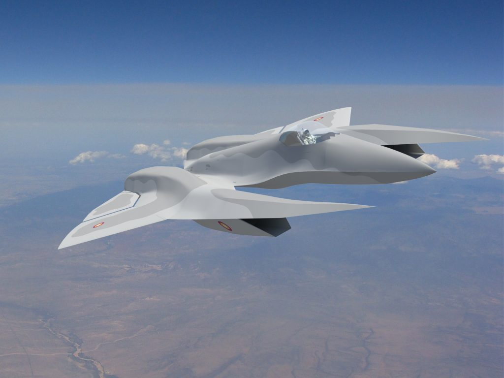
To reduce aircraft Infra-Red (IR) signature the aircraft features titanium and titanium diboride foam metal sandwich structures, including these heat managing external skins. As a high speed aircraft, the SM-39 is designed for heat management. At low, subsonic combat speeds, the same skins that protect the SM-39 at Mach 3+ will help to insulate the SM-39’s interior to reduce the overall heat signature due to aircraft internal heat sources. Coupled with the aircraft’s active heat management system, including avionics cooling, overall heat signature is actively managed from within the airframe. To reduce powerplant signature, the SM-39 will divert both boundary layer air and a portion of air from the engine air intakes into a powerplant cooling system that ducts around the exterior of the engine. This ducting system is located between the engine and the airframe internal structure and is designed specifically to blanket the engine’s combustion, turbine and afterburner modules in a lower temperature environment during cruise and non-afterburning, maximum power flight.
To reduce visual signature the SM-39 will benefit from active skin technology in addition to low-visibility paint schemes. To reduce aural signature, the SM-39 will feature an active noise cancellation system developed by a primary industry team member.
Qualification
The SM-39 Razor will be relevant category FAA FAR Part 25 Type certified for day/night VFR/IFR operations in the the Normal, Utility and Aerobatic Categories. The SM-39 manufacturing process and production line will be FAA Production Certified. The SM-39 will be certified for single pilot IFR operations and to fly in known icing conditions. The SM-39 will have a certified flight envelope cleared for stalls, spins, aileron and barrel rolls, Chandelles, Cuban Eights, Immelmans, Split-S and additional maneuvers.
The SM-39 is engineered to comply with relevant MIL-STD and MIL-SPEC requirements, including MIL-HDBK-516B Airworthiness Certification Criteria in accordance with AFPD 62-6 and AFI 62-601 and will be properly certified/qualified to meet acquisition requirements for service as a USAF/USN/USMC weapon system. The SM-39 will be qualified to allow for U.S. Allied/Mentor operation. The SM-39 will be flight tested at the USAF AFFTC and other qualified test centers including NAS Pax River. SM-39 stores qualification will be performed at the AFFTC and NAS China Lake. The SM-39 will be qualified to carry all stores identified within Warload and Stores chart as presented within this document. SM-39 aircraft for Export will be certified and tested for End Users in accordance with local existing laws and regulations.
Operational Costs
The SM-39 Razor will have an operational Cost Per Flight Hour (CPFH) of approximately $10,117 per hour, including an aircrew cost of $586 per hour and a fuel cost of $4,360 per hour. The CPFH estimates assume an annual utilization rate of 350 FH/PAA.
The SM-39 has been designed for an operational service life of 20,000 hours, accumulating an average of 350 hours per annum. Aircraft fatigue life will be based upon 40,000 takeoffs and landings (cycles). The aircraft maximum design load factor limit is +7.5-g and -3.75-g at Maximum Gross Takeoff Weight (MTOW) with maximum external stores (25,000 lbs) and full internal fuel (30,000 lbs).
Stavatti projects SM-39 Razor to require 17.88 MMH/FH. Stavatti projects that the aircraft will exceed a Mission Capable (MC) availability rate of eighty-nine percent (89%) with ninety-eight percent (98%) likely. Aircraft Fleets of 12 or more aircraft are projected to sustain mission capable/mission availability rates of eighty-five percent (85%) to ninety-five percent (95%) or better.
Designed for operation from austere, unprepared locations and semi-prepared surfaces, the Razor is designed for operation in arid, desert, tropical, arctic and sea-salt environments and is capable of functioning without reduction in mission capable rates in -25°C to 55°C environments. The Razor will be equipped and FAA certified for single-pilot day/night IFR operations. The Razor will be able to operate in ground conditions from -25°C to 55°C and in flight conditions from -55°C to 60°C.
Disclaimer and Notice of Restricted Configuration
To ensure the protection of PROPRIETARY and ADVANCED DEFENSE TECHNOLOGY, as well as to remain in accordance with the International Traffic in Arms Regulations (ITAR) the SM-39 Razor aircraft configuration as presented within this website, as well as within all associated documents, including but not limited to, aircraft general arrangement drawings, three view drawings and technical drawings of any manner or form are limited to Non-Conformal Artistic Impressions (NCAI) and may not be representative of the actual SM-39 Razor design, prototype aircraft or final production aircraft configurations.
Stavatti reserves the right to present non-representative drawings, renderings and artists renditions of the SM-39 Razor for presentation and marketing purposes that may not represent the final prototype or production aircraft configuration. Furthermore specific aspects of the SM-39 design configuration may be altered for company proprietary or defense technology security purposes, especially during time of war.
Information relating to final aircraft prototype and production configurations is maintained on a Stavatti Need-To-Know (NTK) basis and such information may not be presented within this document. All SM-39 configurations and drawings as presented herein are not necessarily representative of the actual aircraft configuration for security reasons. Drawings and Renderings of the SM-39 Razor as presented in this document are non-representative hypothetical artists renditions only. The SM-39 Razor Configuration is Patent Pending with the US Patent & Trademark Office. The SM-39 Razor and its various concept configurations are the copywritten Intellectual property of Stavatti Aerospace Ltd and its principal designer Christopher R. Beskar.
Performance & Specifications
MODEL
SM-39 Razor
TYPE
Next Generation Air Dominance Fighter, Interceptor and All-Weather Strike Fighter and Fighter Bomber
ACCOMMODATION
Single Pilot Seated on a MK18 or ACES 5 Zero-Zero Ejection Seat or Proprietary Ejection Seat
POWERPLANT
Two 52,400 lbs static thrust NeoThrust™ E1400-SE-520 variable cycle afterburning turbofans with MHD Energy Bypass /or/ Two 50,000 lbs static thrust class GEAE ACE variable cycle afterburning turbofans
STRUCTURE
Semi-monocoque titanium foam metal sandwich construction throughout with multiple titanium sine-wave spars in the cantilever wings and empennage. Titanium metal ceramics (cermets) used in high temperature regions.
ARMAMENT
Fixed: One Engine Driven Gas Dynamic Directed Energy Laser Weapon or 20mm M61A2 Cannon with 1,000 rds
Expendable: Two internal weapon bays and four external wing hardpoints for carriage of up to 25,000 lbs of stores
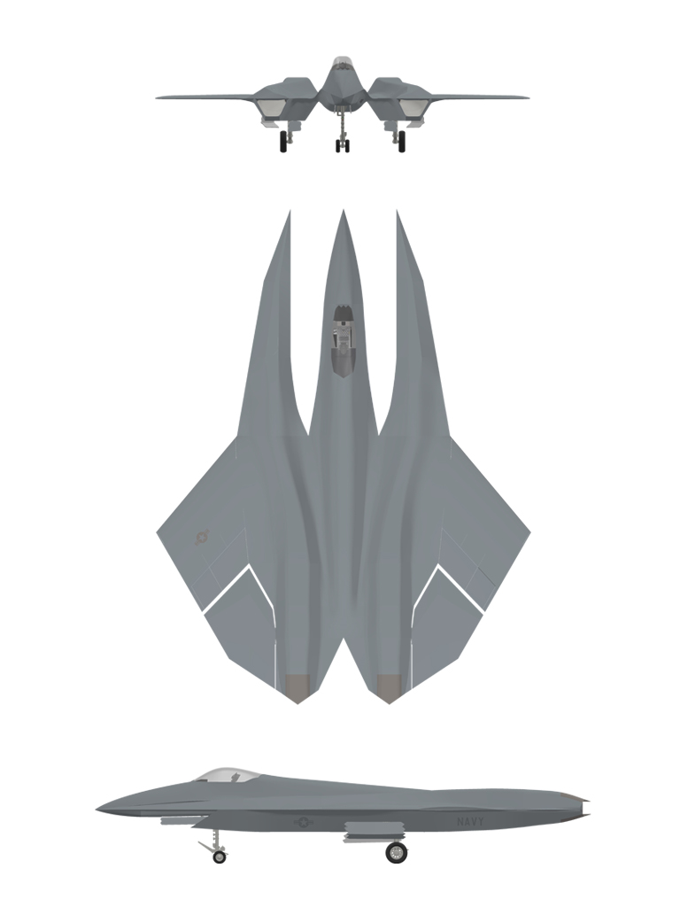
| DIMENSIONS | WEIGHTS & CAPACITIES | ||
|---|---|---|---|
| Wingspan | 53 ft 0 in | Empty Weight | 44,500 lbs |
| Length Overall | 70 ft 0 in | Maximum Internal Fuel (IF) | 30,000 lbs |
| Height Overall | 13 ft 8 in | Max Warload | 25,000 lbs |
| Wing Area | 1,206 sq ft | Max Useful Load | 56,000 lbs |
| Wheelbase | 25 ft 0 in | Typical Combat Weight (TCW) | 66,000 lbs |
| Wheeltrack | 16 ft 9 in | Max Take-Off Weight (MTOW) | 100,500 lbs |
| ESTIMATED PERFORMANCE | ESTIMATED PERFORMANCE | ||
|---|---|---|---|
| Max Level Speed @ SL | 1.40 Mach | Max Speed Range @ 60,000 ft | 470 nm |
| Max Level Speed @ 35,000 ft | 2.40 Mach | Max Speed Range @ 80,000 ft | 1,012 nm |
| Max Level Speed @ 60,000 ft | 4.20 Mach | Max Speed Range @ 90,000 ft | 1,277 nm |
| Max Level Speed @ 80,000 ft | 4.20 Mach | Supercruise Range @ 40,000 ft | 1,700 nm |
| Max Supercruise @ 40,000 ft | 2.00 Mach | Tactical Radius, Air Superiority | 1,400 nm |
| Typical Cruise @ 40,000 ft | 0.90 Mach | Ferry Range-External Tanks | 5,200 nm |
| Typical Cruise @ 60,000 ft | 0.95 Mach | Takeoff-Ground Roll, Takeoff Weight | 946 ft |
| Typical Takeoff Speed @ SL | 136 KTAS | Takeoff over 50 ft, Takeoff Weight | 1,888 ft |
| Typical Approach Speed @ SL | 105 KTAS | Landing-Ground Roll, Landing Weight | 827 ft |
| Typical Landing Stall Speed @ SL | 91 KTAS | Landing over 50 ft, Landing Weight | 1,250 ft |
| Max Initial Rate-of Climb @ SL | 99,485 ft/min | Service Ceiling Exceeds | 100,000 ft |
SM-39 Razor General Arrangement
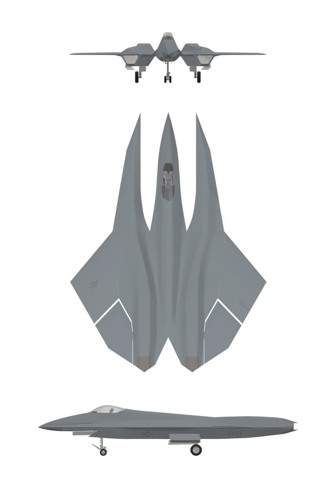
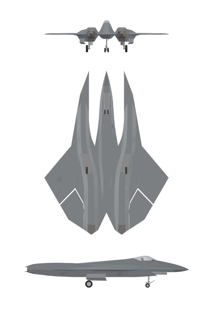
Cost
The SM-39 Razor is now under development and is not currently in production. Qualified customers are invited to place Pre-Orders for SM-39 Razor aircraft at this time. Upon entering production, the Per Unit Flyaway Cost (Flyaway Cost) of SM-39 Razor aircraft will be dependent upon the specific model, model block configuration, customer selected weapon system sensor-avionics-instrumentation-electronic warfare-armament systems package, and all related support equipment specific to an individual aircraft, not including fixed or expendable external stores (external or drop tanks, ordnance, pods and pylons), spares or ground support equipment.
Based upon a Standard Weapon System Configuration (SWSC) developed for each member of the SM-39 in support of the marketing and export of aircraft to NATO allied air defense forces, a Rough Order of Magnitude (ROM) Per Unit Basic Flyaway Cost has been projected for the Razor. Projected ROM Flyaway Costs for Block 10, Low Rate Initial Production (LRIP) SM-39 Razor aircraft of Basic SWSC are as provided. All projected ROM costs herein provided are approximate estimations issued to assist potential procurement bodies for future force budgetary planning only. Projected ROM costs are not contractually binding. The current year Basic Aircraft Flyaway Cost is:
$85,000,000
The Basic Per Unit Flyaway Cost of SM-39 Razor aircraft will be approximately $85,000,000 (eighty-five million) United States Dollars (USD), depending upon specific model and configuration.
These ROM, approximate Flyaway Costs apply to one (1) SM-39 Razor aircraft (Stavatti Model 39S or 39T) of Standard Weapon System Configuration (SWSC). In an effort to simplify the marketing and distribution of the Razor weapon system worldwide, Stavatti has developed the SWSC. The SM-39 SWSC represents a common SM-39S/T configuration which is readily suitable for mass production and expedient delivery to the customer. Stavatti customers will be able to purchase SM-39S/T SWSC aircraft at a specified flyaway cost plus applicable duties and export/delivery expenses.
SM-39S/T SWSCs are specified within the SM-39S/T Configuration Control Statement (CCS) document as issued by Stavatti Aerospace Ltd. for specific SM-39 models as appropriately configured for specific domestic and allied customers. Contact STAVATTI or visit SM-39 Razor Product Literature for a copy of an appropriate CCS. A portion of the avionics, displays, armament and related systems associated with the SM-39 SWSC are also indicated in the Specifications page of this website. The following support documentation, options, equipment and material is also included with each SM-39S/T of SWSC:
U.S. Standard Airworthiness Certificate, Export Certificate of Airworthiness, Weight and Balance Data Sheets/Weight and Balance Plotter, Aircraft/Engine/Armament System Log Books, Abbreviated Checklist, Flight Manual, Pilot‘s Operating Manual, Avionics Wiring Diagrams, Hydromechanical Systems Manual, Maintenance Manual (Airframe), Illustrated Parts Catalog (Airframe), Wiring Diagram Manual (Airframe), Weight and Balance Manual, Air Combat Manual, Special Combat Operations Manual, Advanced Training Instructional Manual (SM-39T), Component Maintenance Manual, Structural Repair Manual, System Control Code Programmers Manual, Illustrated Tool and Equipment Manual, Nondestructive Inspection Manual, Engine Maintenance Manuals, Engine Illustrated Parts Catalogs, Parts Warranty Listing, additional miscellaneous information concerning engine, airframe, avionics and armament support, Aircraft Tie-Down Kit (including tie-down anchors and cable, wheel chocks, control locks, pitot-static port covers, etc.), Aircraft Full Canopy Sunshade/Cover, Basic Aircraft Tool Kit, Aircraft Emergency Survival Kit, HGU-86/P pilot flight helmet and accompanying flight/anti-g suit of customer specified sizing (Note: SM-39T aircraft include two helmets and anti-g suits), 24 hours of Stavatti provided SM-39 operational ground schooling/orientation for one flight officer, 24 hours of Stavatti provided SM-39 maintenance and service ground schooling/orientation for one maintenance officer, 5 hours of SM-39 orientation flying in a Stavatti owned and operated SM-39 for one flight officer, Custom Paint Scheme consisting of up to 10 base colors and up to 25 trim colors as well livery/noseart, 1,000 rounds of installed 20 mm ammunition for M61A2 cannon or appropriate rounds for alternate fixed armament, Full Fuel consisting of JP-8 installed in aircraft, additional equipment and a 2,000-Hour ‘Nose-to-Nozzle’ Manufacturer’s Warranty.
All publications, documents and manuals will be provided in both hardcopy bound print as well as digital, CD-ROM and Aerofiche format. In addition to documentation supplied by Stavatti Military Aerospace, additional documentation may be provided detailing the operation/maintenance of specific aircraft systems by specific aircraft system manufacturers. Stavatti will provide Service Bulletins, Service Letters, Air Worthiness Directorates and manual revisions for the duration of aircraft operational service life.
The Flyaway Cost of the SM-39S/T does not include the cost of any spares, external stores/armament, or other logistical support that may be associated with a weapon system procurement contract. The additional costs associated with the provision of spares, external stores/armament, Contractor Logistical Support or any other indicative cost options, maybe provided by Stavatti. All Flyaway Cost data provided herein is not contractually binding and are conceptual in nature.
The noted Flyaway Costs only apply to the SM-39S/T of SWSC. The SM-39S/T SWSC does not represent aircraft configured to satisfy specific customer requirements. Stavatti desires to satisfy all customer needs and requirements. In so doing, the SM-39S/T will employ open avionics and systems architecture allowing the SM-39S/T platform to employ a wide variety of avionics, armament and sensor systems. Customers are invited to procure aircraft which employ customized systems configurations, as specially developed by Stavatti. The Flyaway Cost of SM-39S/T aircraft of customized configuration will be dependent upon the systems specified and is determined only upon assessment of the specific configuration. Generally, the Flyaway Cost of SM-39 aircraft as projected will fall between $85 million and $95 million dependent upon ultimate configuration.
AVAILABILITY
The SM-39S/T Razor series of aircraft is currently under development by Stavatti Aerospace Ltd.-Tactical Air Warfare Systems Division. The SM-39 is not currently in production and is not available for procurement at this time. Stavatti is accepting and receiving orders for the SM-39 at the present time, hence initial production aircraft will be produced in satisfaction of backlog orders. The estimated time-frames for initiation of Low Rate Initial Production (LRIP), Initial Operational Capability (IOC) within end-user air defense arms and Full Rate Production (FRP) are as projected:
| AIRCRAFT MODEL | PROGRAM PHASE | TIME-FRAME |
|---|---|---|
| SM-39 RAZOR |
LRIP: | Contact Stavatti |
| IOC: | Contact Stavatti | |
| FRP: | Contact Stavatti |
Stavatti reserves the right to adjust, modify, expedite, cancel or otherwise enhance the projected dates for SM-39 Razor series LRIP, IOC or FRP at our discretion. All program phase time-frame estimates are for the benefit of future force program budget planners and are non-contractually binding.
Prior to entering Full Rate Production (FRP), the SM-39 Razor must complete a comprehensive RDT&E program, followed by twelve (12) to twenty-four (24) months of Low Rate Initial Production (LRIP). The SM-39 RDT&E program will result in the fabrication of a minimum of three (3)SM-39 Razor Prototype Air Vehicles (PAVs) of each series model (SM-39S & SM-39T), which will undergo over 2,000 hours of flight testing. Conclusion of the flight test program will result in FAA FAR 25 type and production certification as well as applicable MIL SPEC qualification.
LRIP consists of a one to two year gradual ramp-up of production, focused upon the manufacture of twenty five (25) to fifty (50) SM-39 Razor production aircraft. All aircraft produced during LRIP are considered Production Articles. The first one (1) to three (3) SM-39 Razor produced in LRIP will likely remain in possession of Stavatti to serve as company demonstrators. The remaining SM-39 Razors produced during LRIP will be delivered to satisfy customer orders. Due to security restrictions, Stavatti does not openly publish the current backlog for SM-39 Razor orders. Stavatti will begin satisfying this backlog through LRIP.
Full-Rate Production will result in the production of between 50 and 100 SM-39 Razor aircraft annually, with an anticipated SM-39 delivery lead time of 12 months. All SM-39 production availability schedules are subject to change.
PURCHASE
To purchase or order the SM-39 Razor Next Generation Air Dominance Fighter please complete and submit the following Letter of Intent (LOI) or Purchase Agreement (PA) forms and if a Non-USA entity also complete and submit an executed DSP-83 Nontransfer and use certificate:

SM-39 Razor aircraft are marketed and sold directly by Stavatti Aerospace Ltd. to the end user as a Direct Commercial Sale (DCS) with exception of specific systems which require a Foreign Military Sales (FMS) component including, but not limited to: IFF and COMSEC/TEMPEST related systems and equipment. Furthermore, all Global Positioning Systems (GPS) receivers incorporating a PPS (Y) Interface must be approved for export through the Joint GPS Program Office.
Stavatti reserves the right to market and sell the SM-39 Razor through the U.S. FMS program for purposes of assisting customers who desire the procurement of major weapon systems with military credits or direct program/operational support from the U.S. DoD.
To simplify the procurement process, Stavatti prefers to structure SM-39 Razor procurement contracts as Fixed Cost Contracts (FCC). Customers may elect to procure SM-39 Razor SWSC aircraft or SM-39 Razors configured for customized end user requirements. In the event customers wish to procure SM-39 Razor SWSC aircraft, there is a distinct possibility that aircraft may be procured from existing Stavatti inventory, thereby significantly reducing delivery lead-time.
If customers desire an SM-39 Razor of custom configuration, the procurement lead-time may increase from 6 to 12 months due to the lead-times associated with the procurement of specific aircraft systems including powerplant, avionics, displays and armament. It is for this reason that the Standard Lead Time for the procurement of SM-39 Razor aircraft is estimated at 12 months from date of contract signing.
Stavatti does not employ a standard SM-39 Razor series FMS procurement process. All SM-39 Razor procurement performed under FMS must be coordinated on a case-by-case basis. Stavatti’s standard SM-39 Razor DCS procurement process for all SM-39 aircraft is as follows:
1) Customer provides Stavatti with a Letter of Intent (LOI). An LOI is a statement indicating that the customer (client nation) intends to enter into a binding contract for the procurement of a specified number of SM-39 aircraft. The LOI must include information relating to the number, model and configuration which the customer wishes to procure, the address of the procurement body, a signature of a qualified purchasing representative of the procurement body and the address of the delivery destination of the SM39 aircraft.
2) Stavatti will submit forms DSP-5 and DSP-83 as appropriate to the State Department-Directorate of Defense Trade Controls (DDTC) to obtain the necessary export licenses associated with the SM-39 procurement by the specific customer/client nation. Export licenses are not required for domestic sales to the US DoD/government user agencies. Once an approved export license is received by Stavatti, the customer and Stavatti may proceed with contract draft and signing.
3) Customer and Stavatti draft and enter into/sign a SM-39 Razor Purchase Agreement (PA) or Procurement Contract (PC). The PC will specify the precise configuration of the SM-39 aircraft to be procured including powerplant, avionics, instrumentation, escape systems, armament, APU, armor plating, sensors, EW suite, tires, paint scheme and livery, warranty, associated support equipment, etc. Delivery destination, anticipated delivery date and total contact value will be specified, as well as all other information necessary to produce and deliver the contracted SM-47 aircraft to the customer in their desired configuration. The Customer must ensure the PC is accompanied by a Contract Initiation Payment (CIP) valued at ONE THIRD (1/3 or 33.3%) of the Total Contract Value to be paid to Stavatti.
4) Stavatti completes the production of SM-39 Razor aircraft to the “Green” or Un-Painted/Pre-Final Integration stage. Prior to “Painting” and completing final integration of aircraft armament, sensor, avionic and EW systems, the Customer is required to provide a Green Aircraft Payment (GAP) valued at ONE THIRD (1/3 or 33.3%) of the Total Contract Value to be paid to Stavatti. Once the GAP is received by Stavatti, “Green” aircraft enter the painting/ final integration phase.
5) Stavatti completes and delivers the SM-39 Razor aircraft as specified in the PC. Upon delivery (or upon completion in the event the Customer receives/takes possession of the completed aircraft directed at the factory) of the procured SM-39 aircraft to the customer, the balance of the total contract value, equal to the remaining ONE THIRD (1/3 or 33.3%) of the Total Contract Value, must be paid to Stavatti.
Stavatti will receive payment for domestic SM-39 Razor sales by wire transfer of funds, certified check, United States Dollars/Federal Reserve Notes (USD/FeRNs), gold or alternate precious Platinum Group Metal (PGM). Stavatti will receive payment for foreign export SM-39 Razor sales by wire transfer of funds, United States Dollars/Federal Reserve Notes (USD/FeRNs), gold or alternate precious Platinum Group Metal (PGM).
EXPORT
In compliance with the Arms Export Controls Act (AECA) and the International Traffic in Arms Regulations (ITAR: CFR 120-130), Stavatti restricts the marketing and sale of the SM-39 Razor air weapon system to qualified U.S. and NATO allied air defense arms. In support of current U.S. Arms Embargoes as issued by the U.S. State Department, Stavatti will not export SM-39 Razor aircraft to any of the following nations:
Belarus, Burma, Central African Republic, People’s Republic of China, Cuba, Democratic Republic of the Congo, Eritrea, Haiti, Iran, Kyrgystan, Lebanon, Libya, North Korea, The Russian Federation, Somalia, Sudan, Syria, Venezuela, Zimbabwe
Stavatti recognizes that the status of State Department Arms Embargoes is in constant flux with nations being added or removed from the Arms Embargo List from time to time. Stavatti therefore encourages parties and potential customers interested in procuring SM-39 Razor series aircraft to visit the State Department-Directorate of Defense Trade Controls (DDTC) Website at: https://www.pmdtc.org/ for a current State Department Embargo Reference List.
Prior to marketing the SM-39 Razor series to any potential customer nation, Stavatti contacts DDTC to receive “Prior Approval To Market.” Once prior approval is received, Stavatti initiates a comprehensive marketing program which consists of information and support material which is unavailable to the Public Domain. Prior to issuance of a production contract or purchase order, Stavatti submits an export license application (DSP-5 and DSP-83, etc.) for the purpose of obtaining an export license in support of the anticipated contract or purchase order. The export license application must be accompanied by attachments, some of which must be completed in-whole or in-part by the potential customer/procurement body. Furthermore, a Letter of Intent (LOI) or similar official document including a Procurement Contract must be issued by the intended procurement body to serve as an attachment to accompany the export license application for review by the State Department-DDTC in support of the SM-39 Razor series export licensing process.
Stavatti is a State Department-DDTC registered manufacturer and exporter or U.S. Munitions List (USML) Category I, II, III, IV, VIII (Aircraft), X as well as additional items. Copies of expired, prior year State Department-DDTC Registration Letters are available for review on the Stavati Licenses webpage. Current Registration Letters received from DDTC are not posted online for security purposes.
WARRANTY
Stavatti will assign each SM-39 Razor aircraft with a 2,000 hour, Nose-to-Nozzle, Manufacturer’s Limited Warranty. Stavatti expressly warrants each new SM-39 Razor aircraft (exclusive of powerplant and powerplant accessories as supplied by the manufacturer which are covered under manufacturer warranties), including factory installed avionics, armament, electronic countermeasures and additional factory installed equipment, both standard to the type and optional, to be free from defects in material and workmanship under normal use and service for a period of 2,000 flight hours beginning upon delivery of the SM-39 aircraft to the initial end user.
Stavatti‘s obligation under this warranty will be limited to repairing or replacing, at its sole option, any component or components which within the applicable warranty period are identified by the owner/operator. The repair or replacement of defective components under this warranty will be made by or through any Stavatti or Stavatti approved manufacturer service facility without assessment of fee or cost to the warranty holder for components or labor for removal, installation and/or repair. All import duties, sales taxes and use taxes, if any, on such warranty repairs or replacement components are the sole responsibility of the warranty recipient.
The warranty will apply to any SM-39 aircraft, avionics and fixed aircraft equipment as integrated by Stavatti under production contract by the end user which has been flown, maintained and operated in accordance with Stavatti and other applicable manuals, bulletins, airworthiness directives and other written instructions. The warranty, however, will not apply to SM-39 aircraft, avionics and fixed aircraft equipment as integrated by Stavatti under production contract by the end user which have been subject to misuse, abuse, negligence, accident or battle damage; or which have been altered other than by Stavatti, or contrary to applicable manuals, bulletins, and other written instructions provided by Stavatti, in any way that, in the sole judgement of Stavatti, adversely affects their performance, stability or reliability; or to normal maintenance services (such as powerplant adjustments, cleaning, control rigging, brake and other mechanical adjustments and maintenance inspections); or to the replacement of service items (such as brake linings, filters); or to normal deterioration of appurtenances (such as paint and livery) due to wear.
Each manufacturer procurement contract will incorporate a complete description of all aspects associated with the 2,000 hour `Nose-to-Nozzle’ manufacturers limited warranty. Customers will be able to extend their warranties in 500 hour blocks beyond 2,000 hours for a nominal fee.
LEASING
SM-39 Razor manufactured aircraft will be made available for lease with customer approved credit directly from Stavatti. Stavatti lease programs are subject to U.S. State Department-Office of Defense Trade Controls Approval and may be conducted as DCS or FMS lease programs. FMS lease programs are coordinated through an appropriate U.S. DoD user agency and will generally consist of SM-39 aircraft owned by the U.S. DoD which are then leased, through a DoD negotiated lease agreement, to the end user. FMS lease programs are outside Stavatti’s sphere of influence and parties interested in leasing SM-39 aircraft through FMS are urged to contact the U.S. DoD.
Stavatti DCS leases will involve the lease of Stavatti owned aircraft to the end user. DCS lease terms and arrangements must be negotiated on a case-by-case basis and are dependent upon the type and number of SM-39 aircraft leased and the qualifications of the nation/air arm leasing the SM-39 aircraft. Typically SM-39 Razor SWSC aircraft will be available for 36, 60 and 120 month leases.
All Stavatti lease customers are subject to pre approval requirements. Additional requirements will also apply to qualify for the SM-39 Razor lease program. All lease customers will be required to maintain current Hull and Liability insurance from a qualified aerospace insurance provider throughout the duration of the lease. All leased SM-39 aircraft must be operated by a qualified, SM-39 Type Certified pilot with a current U.S. First Class Medical or equivalent medical certification and no less than 1,500 hours high performance aircraft experience. In the event lease customers are unable to provide a qualified pilot, Stavatti will provide contract pilot services at a negotiated contract cost. A Stavatti lease maintenance agreement will be implemented in conjunction with the standard 2,000 hour ‘Nose-to-Nozzle’ Limited Manufacturer’s Warranty. The lease customer will be responsible for the costs associated with maintenance and repairs on the SM-39 aircraft hull and systems resulting from the combat environment during the time of lease. In the event an SM-39 aircraft is destroyed and/or damaged to such an extent that the aircraft is considered a total loss, during either peace or war, the lease customer will responsible for the remainder of the lease owed due, plus the purchase price of the aircraft at lease end.
Additional requirements, limitations and restrictions will apply. Contact Stavatti for more information regarding the leasing of SM-39 Razor aircraft.
LICENSED PRODUCTION
SM-39 Razor aircraft will be available for licensed production in qualified facilities worldwide. Licensing of SM-39 Razor production is subject to U.S. State Department-Directorate of Defense Trade Controls Approval. Stavatti is responsible for coordinating and negotiating all SM-47 Super Machete licensing worldwide.
Stavatti will permit the production licensing of all SM-39 series models in its entirety, in kit form or, alternatively, industry teaming for the production of SM-39 aircraft in-part or in component form. Licensing arrangements must be considered on a case-by-case basis. Generally, Stavatti assumes license production involves the production of entire SM-39 aircraft from an indigenous producer within a customer nation. To produce the SM-39 under license a customer must first exhibit possession of a qualified, appropriate aircraft production facility capable of producing the SM-39 aircraft to the degree desired (i.e. in whole or in part) as well as qualified engineers and assembly personnel to support the production process. Customers must then pay an initial licensing fee, as well as annual licensing maintenance fees and a royalty on aircraft produced/sold.
Qualified Customers who produce the SM-39 under license will receive significant technical and production support from Stavatti, including access to both Stavatti’s U.S. domestic SM-39 production facility as well as complete familiarization with SM-39 prototypes, production vehicles and demonstrators.
In the event a nation desires to produce the SM-39 under license, but lacks the facilities and equipment to do so, Stavatti can provide total support and assistance with regard to the organization and creation of a suitable production facility.
OFFSET
To address the issue of global fiscal responsibility with regard to necessary defense spending, Stavatti offers numerous Offset opportunities associated with SM-39 procurement.
The standard cost offset associated with SM-39 procurement is the licensed production of SM-39 subsystems and components in the customer nation. Stavatti maintains industry partners worldwide and desires to expand major airframe component/assembly production into your region of the world.
Barter is an offset opportunity which Stavatti will willingly consider. Oil, minerals, and additional goods may serve as suitable barter toward the procurement of SM-39 aircraft. Additionally, Stavatti will take trade-ins from existing nation fighter/trainer/ transport aircraft fleets, serving to reduce overall aircraft procurement costs.


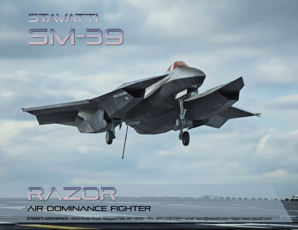
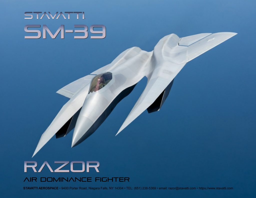
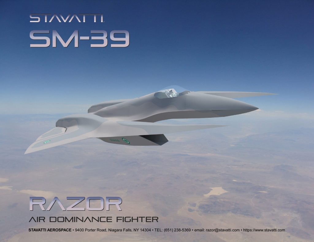


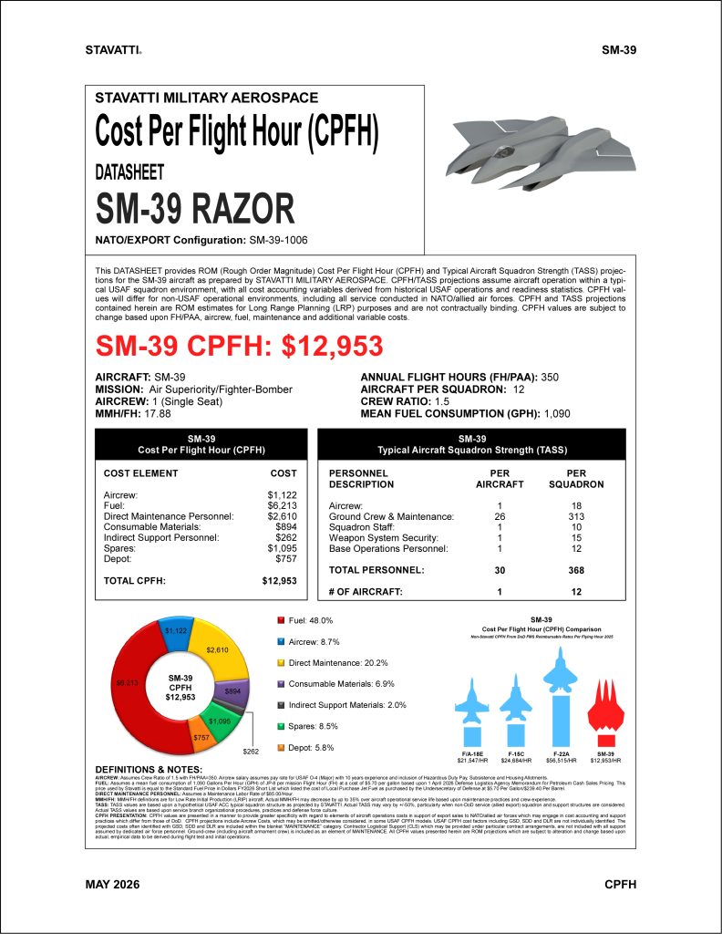


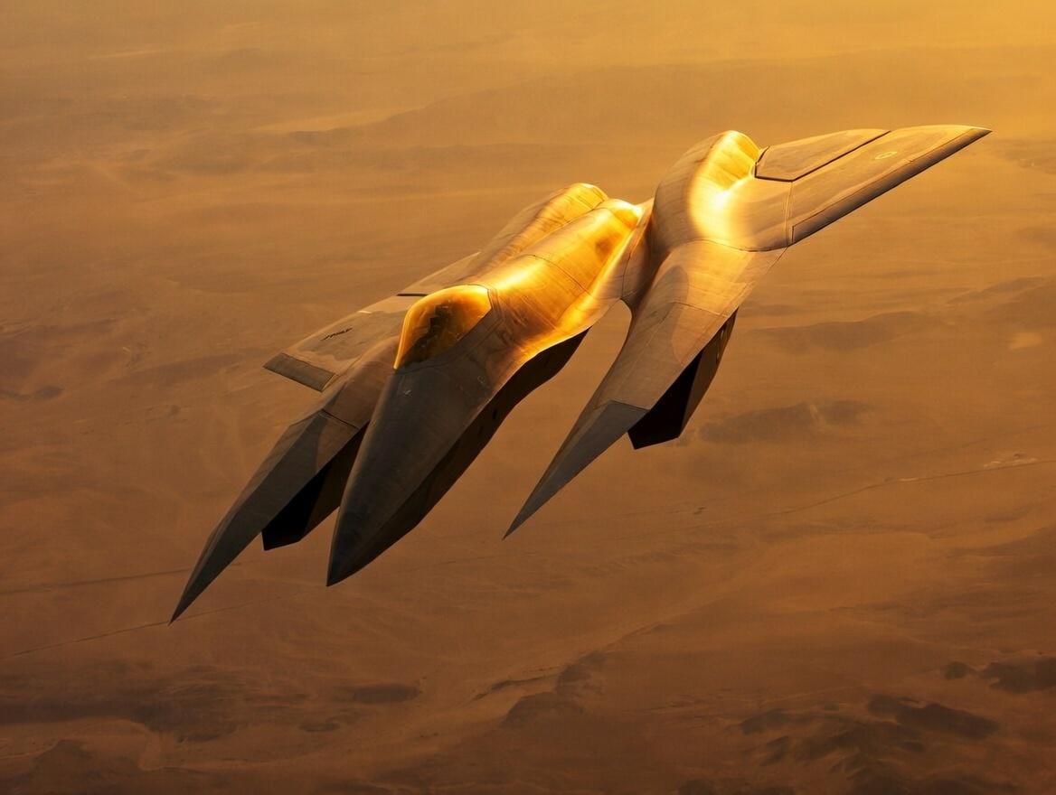
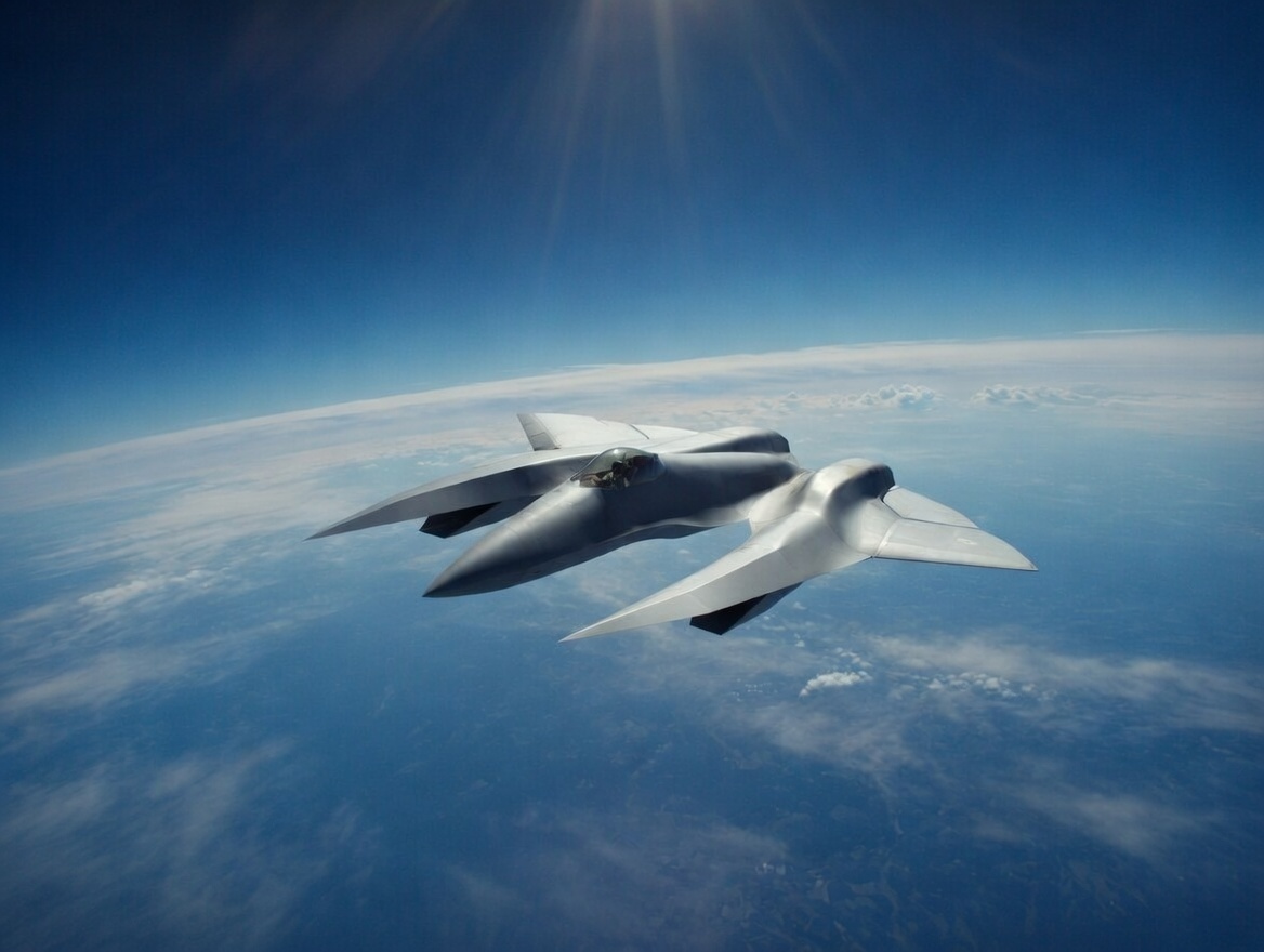
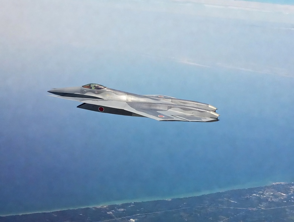
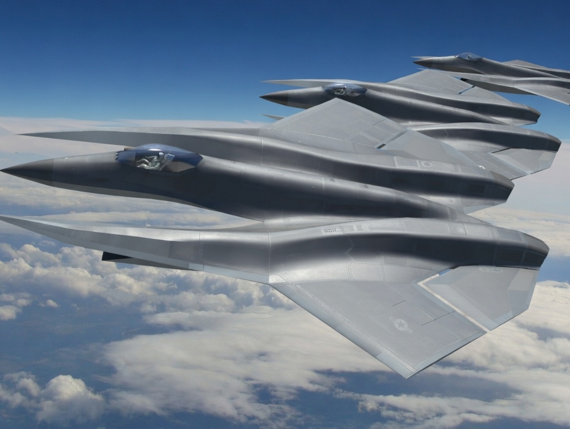
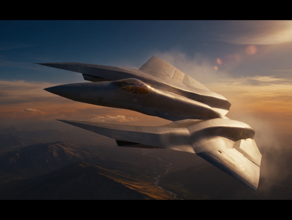
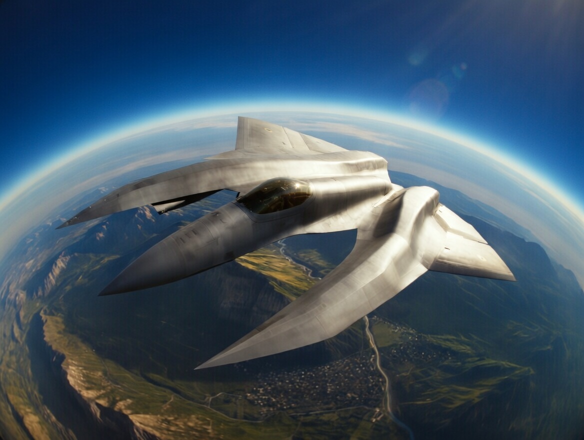
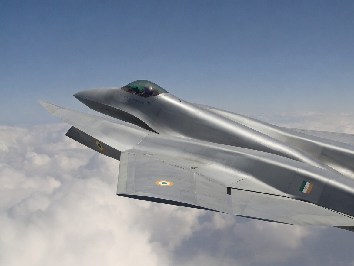
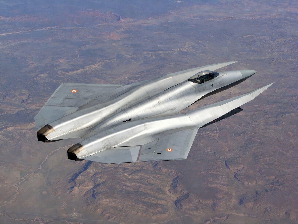
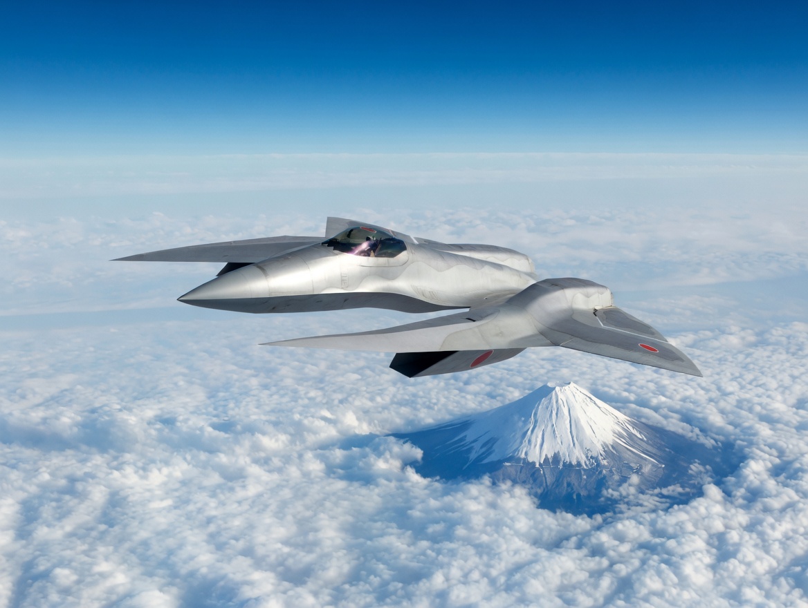
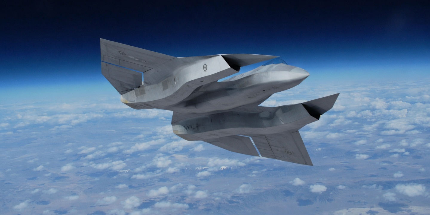
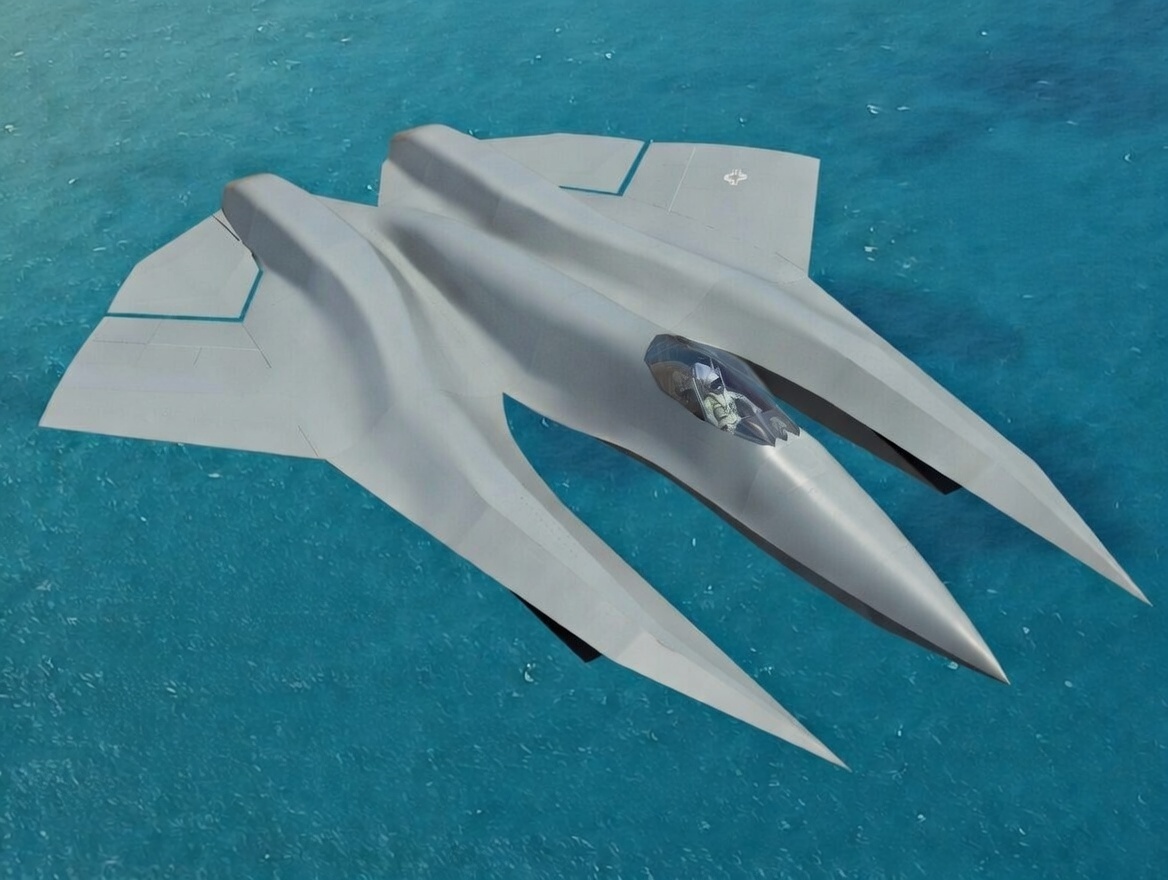
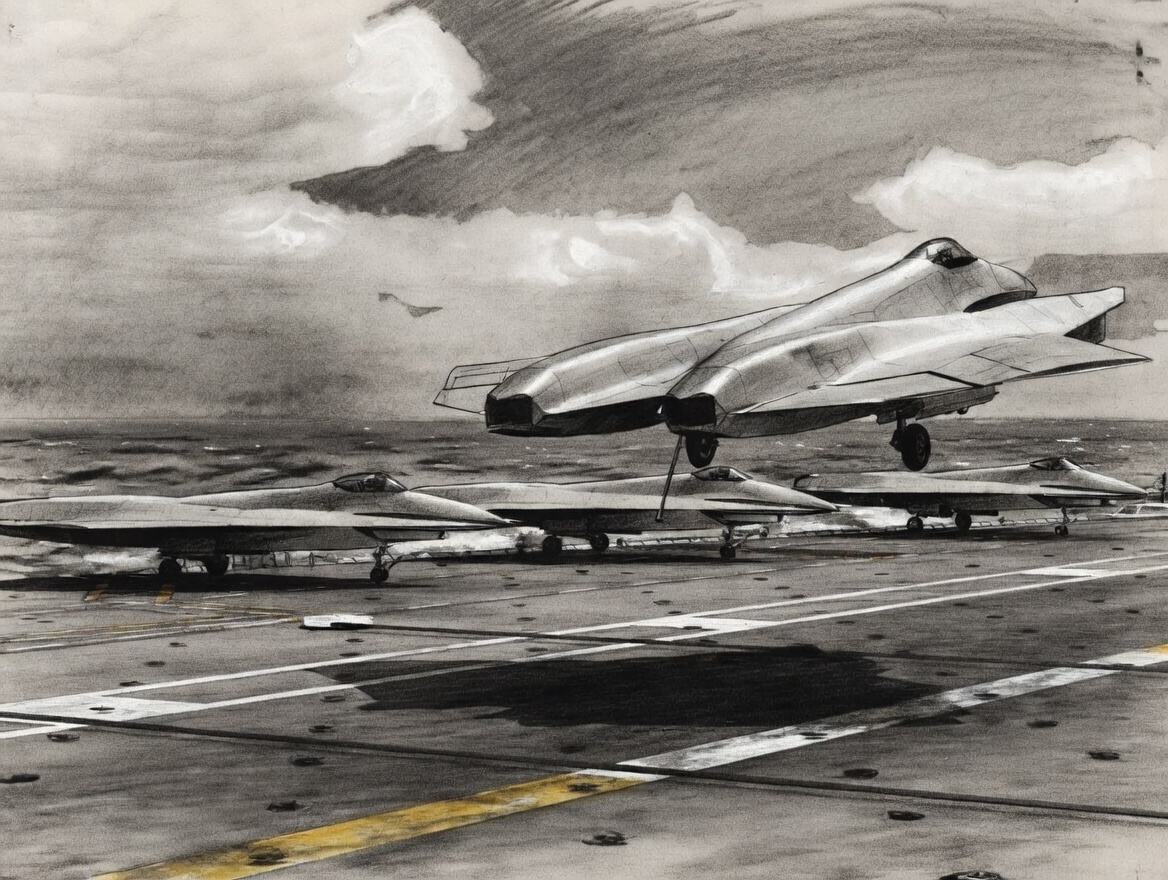
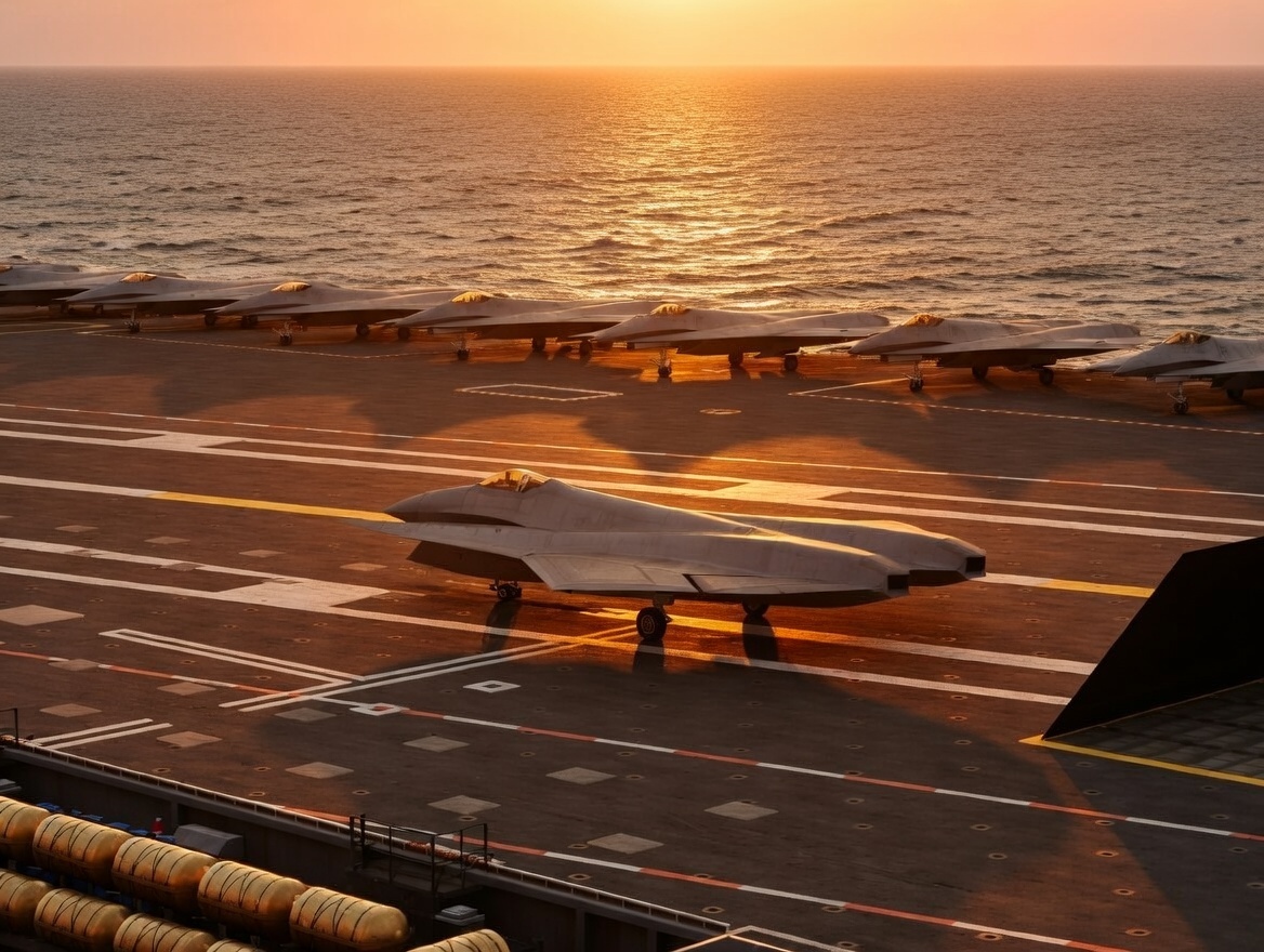
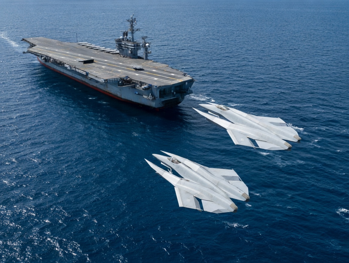
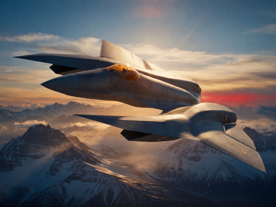
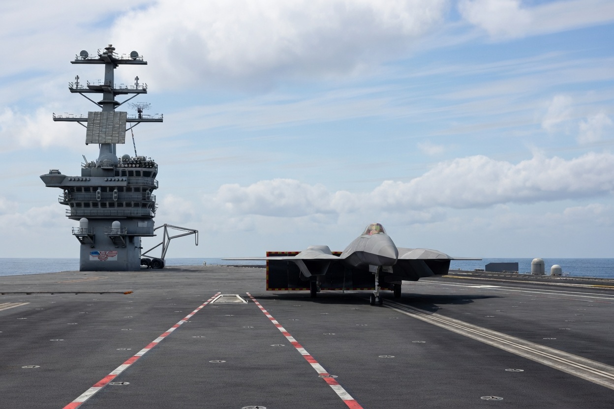
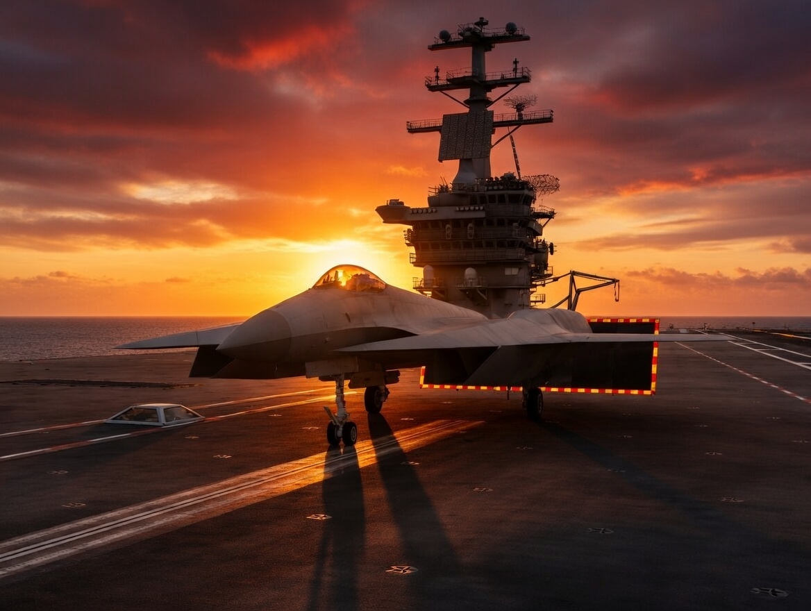
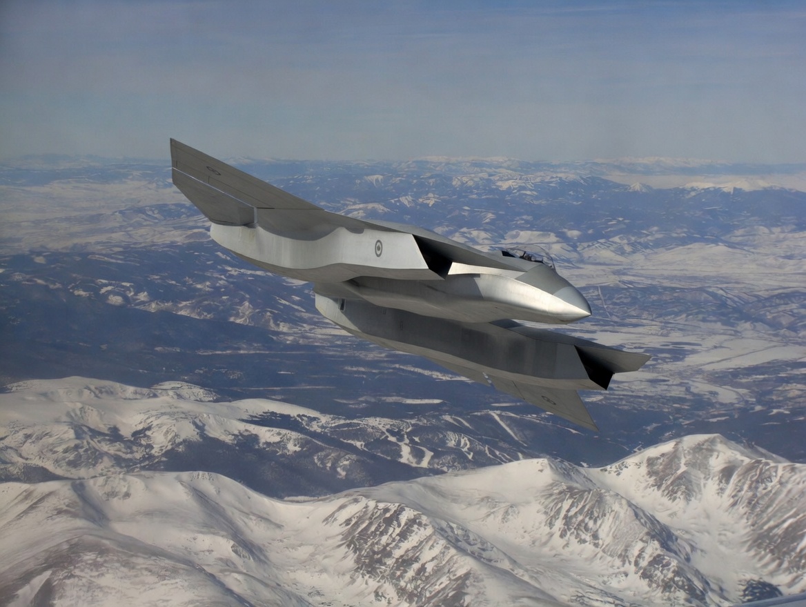
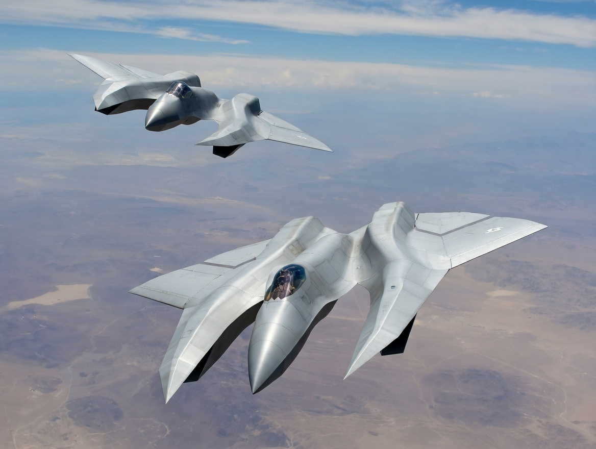
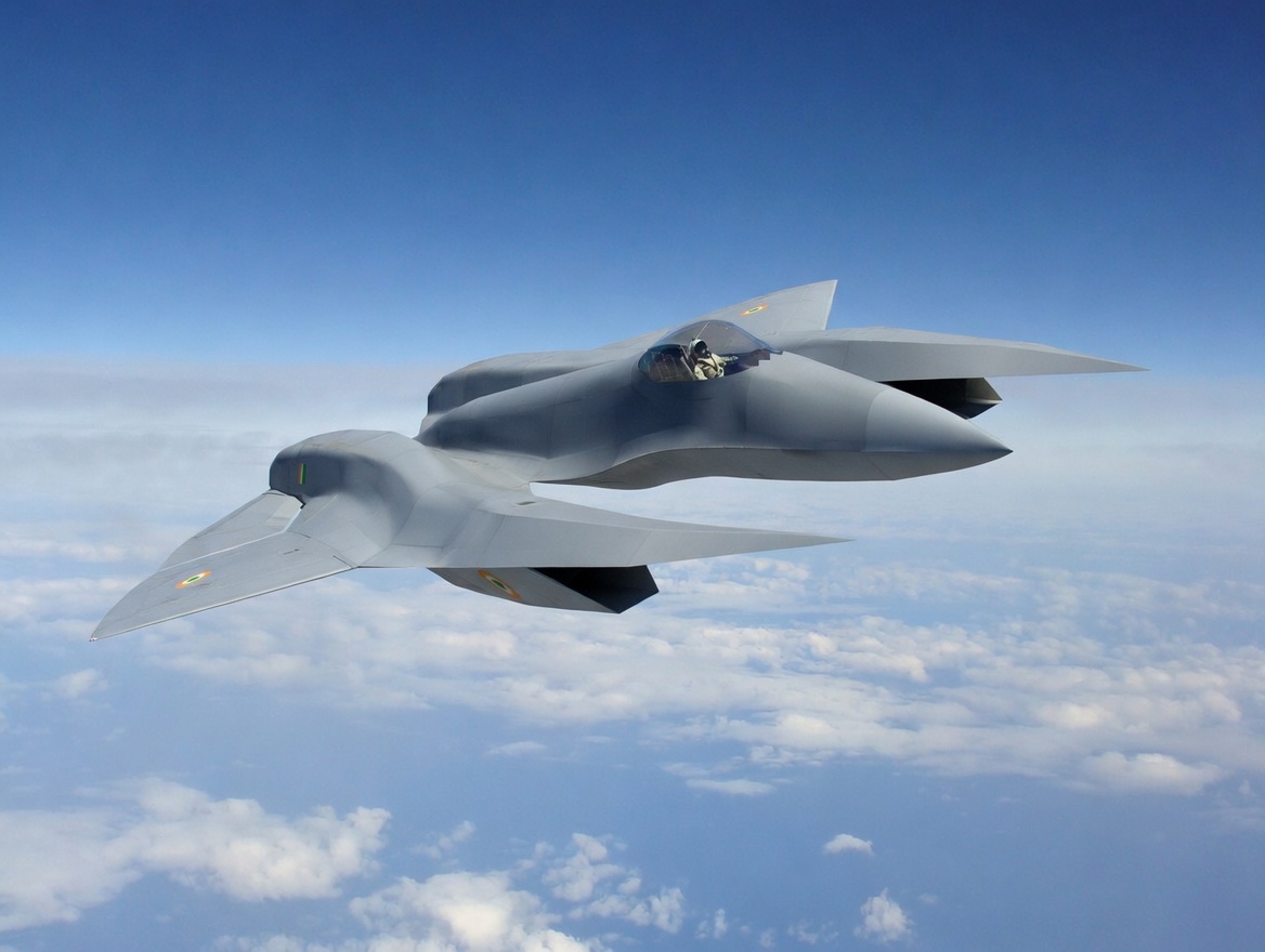
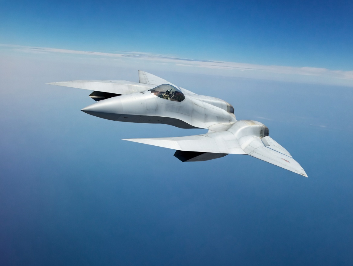
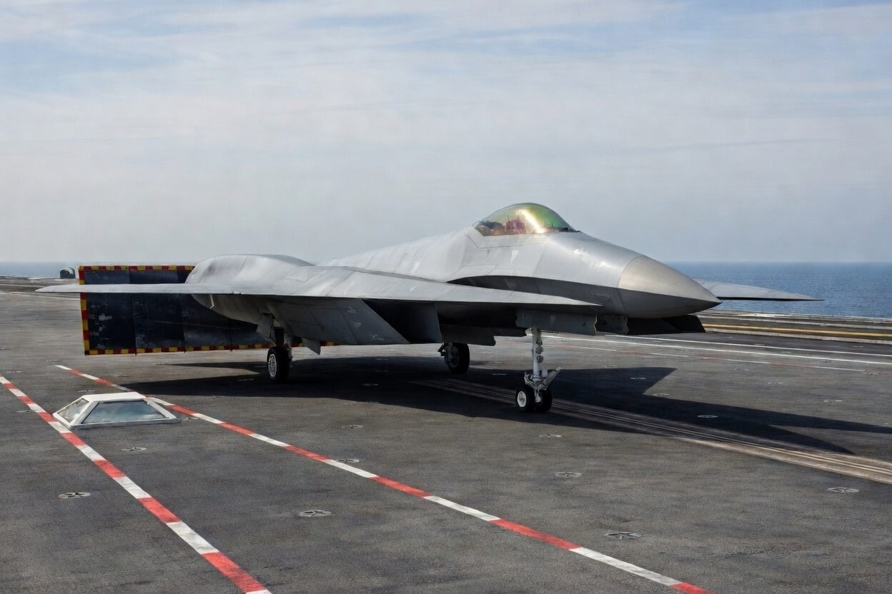
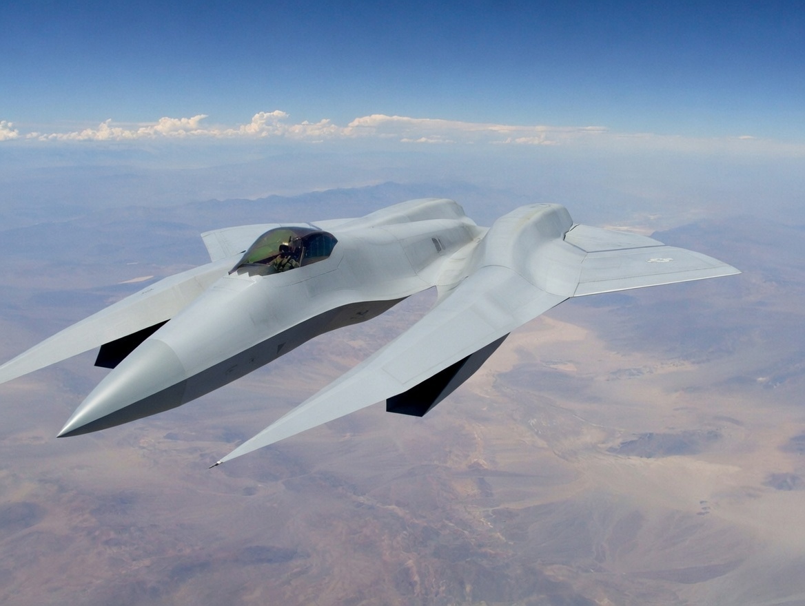
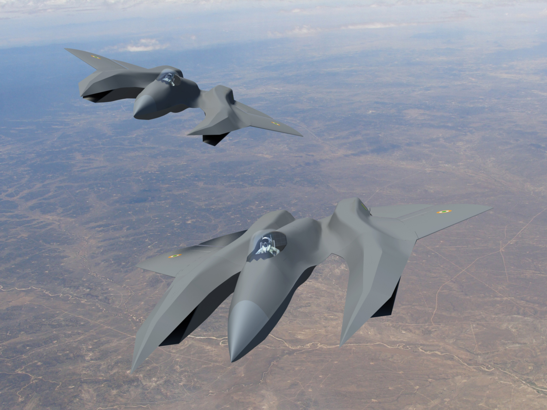
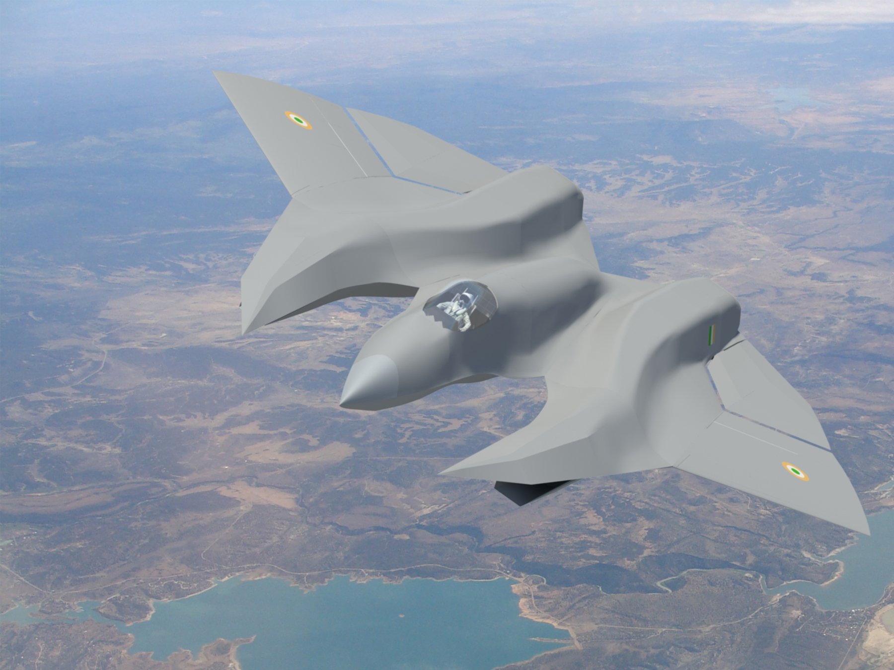
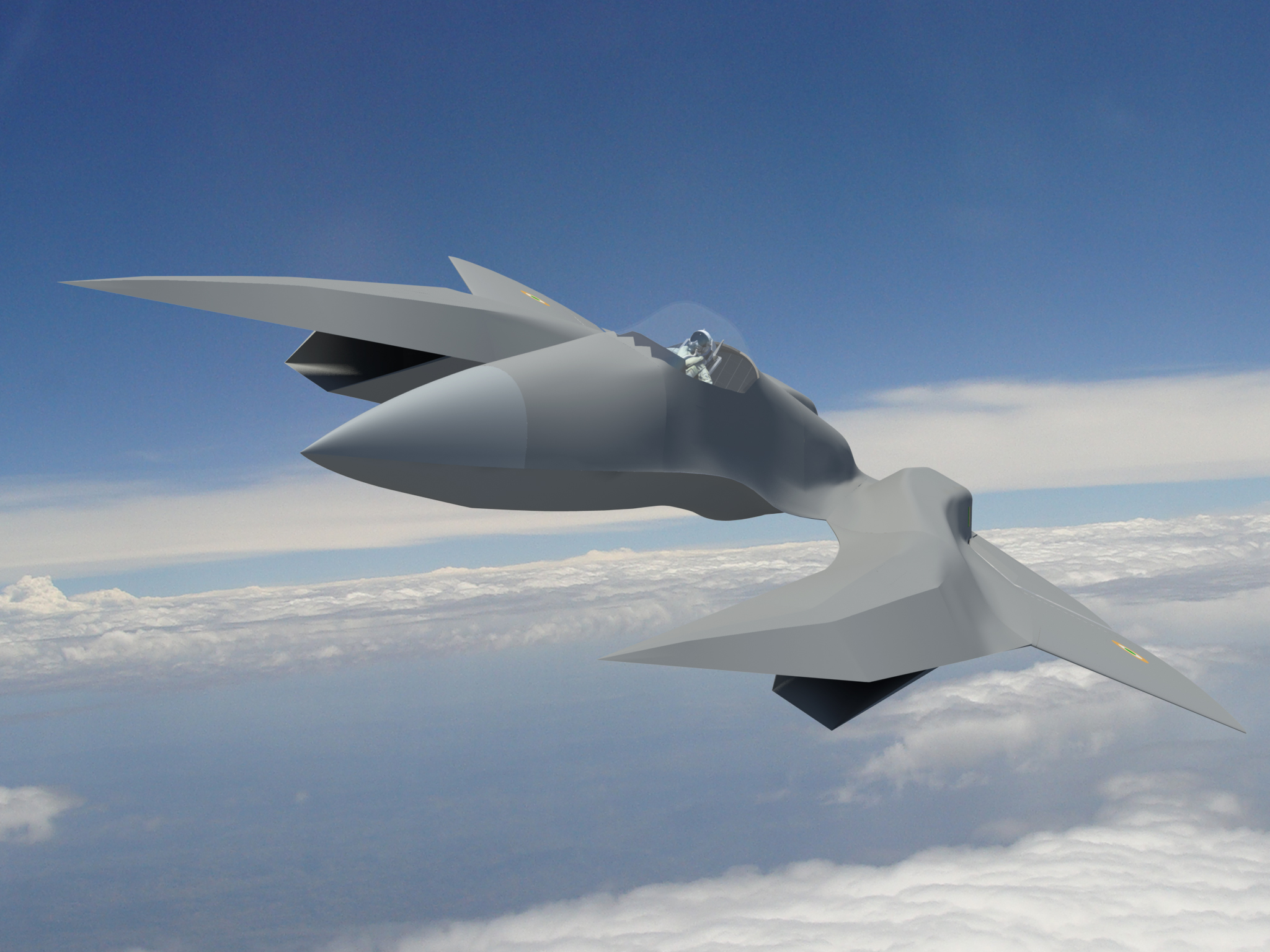
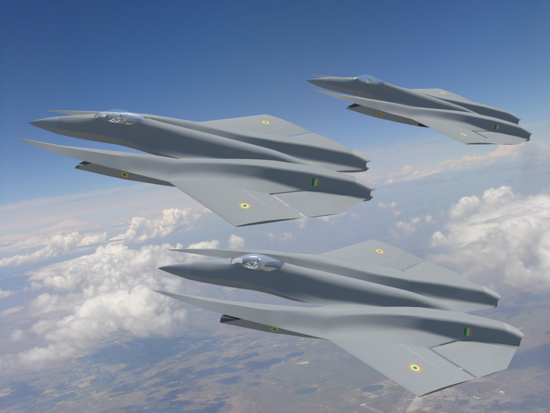
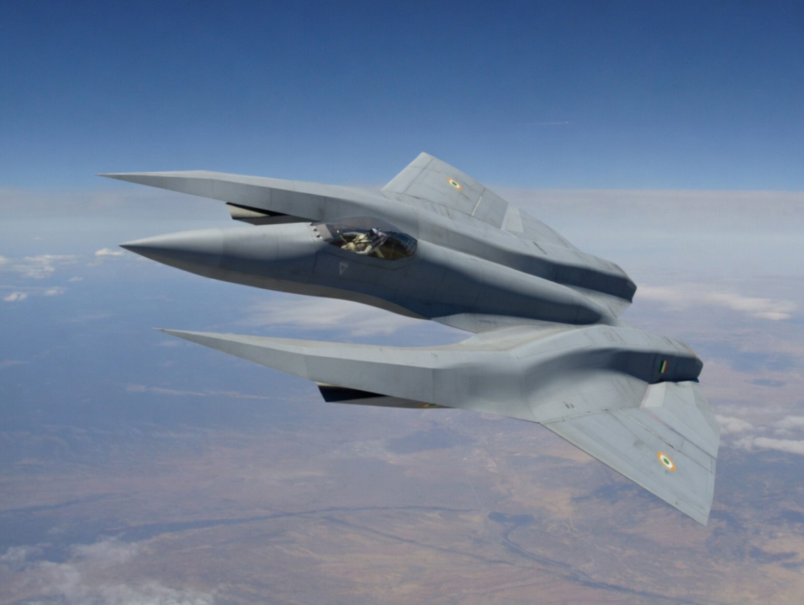
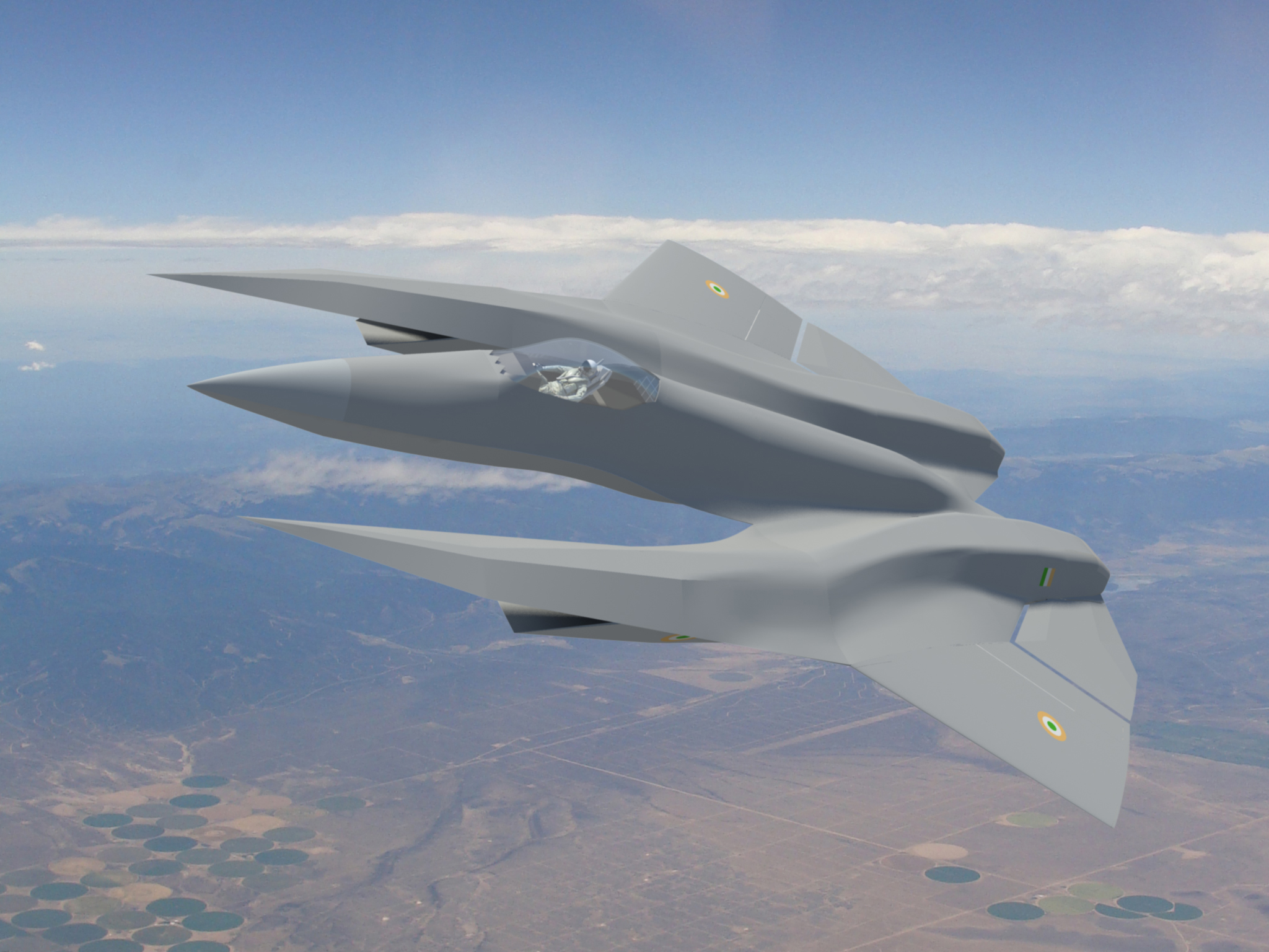
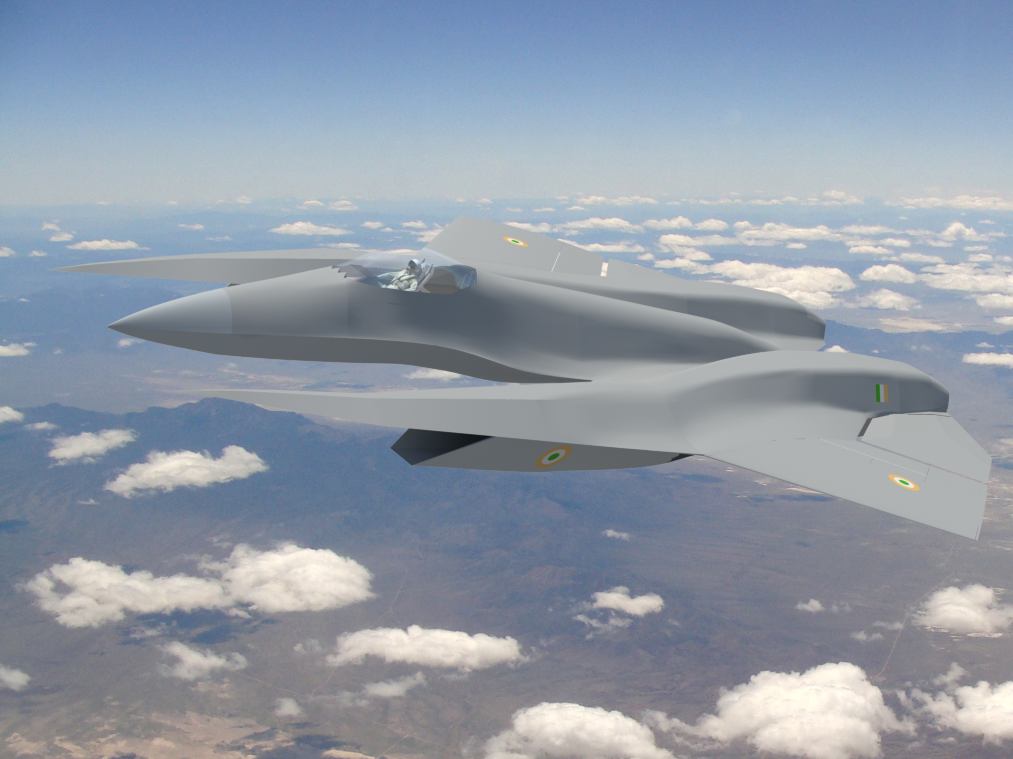
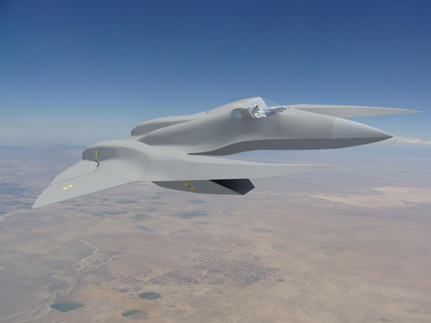
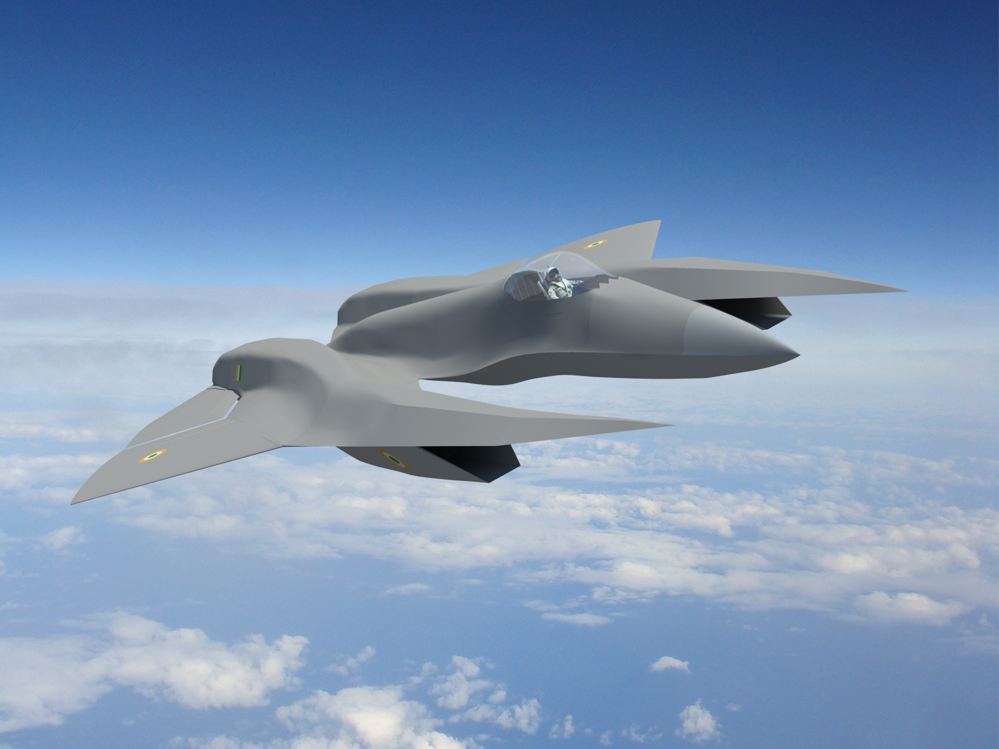
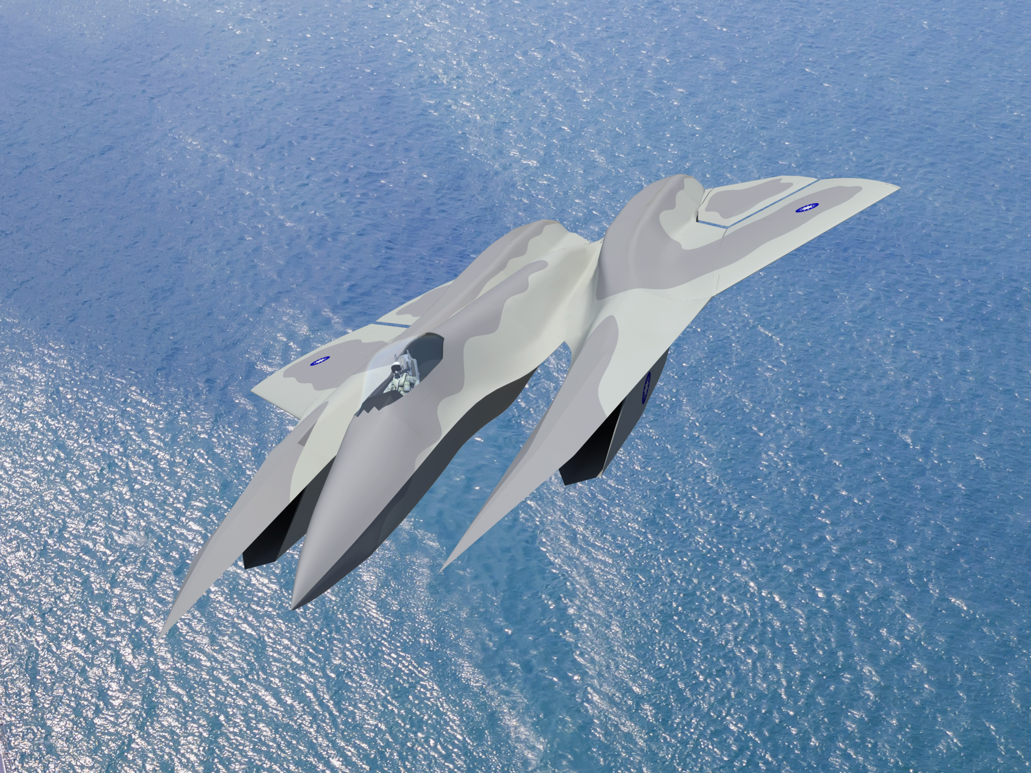
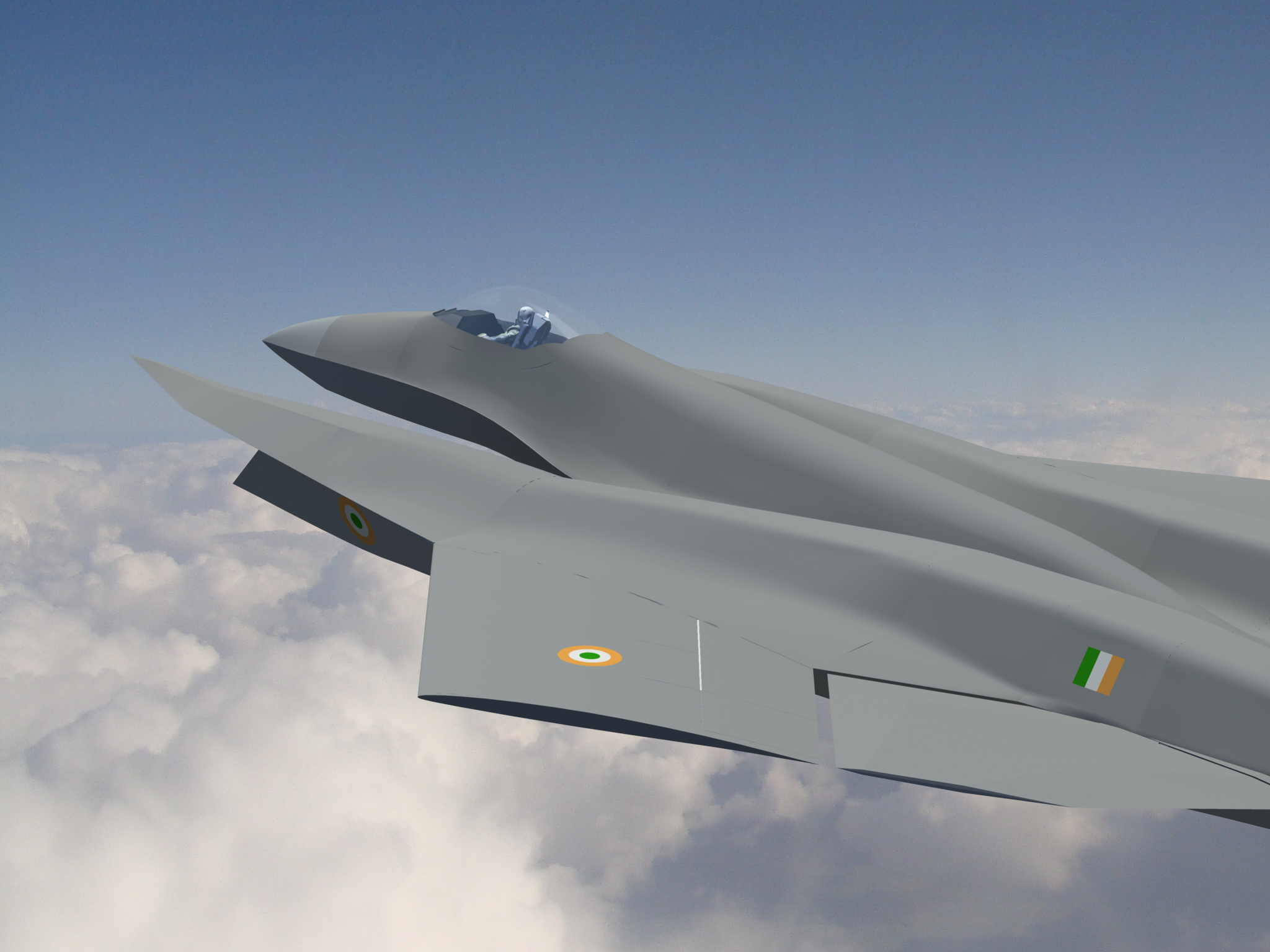
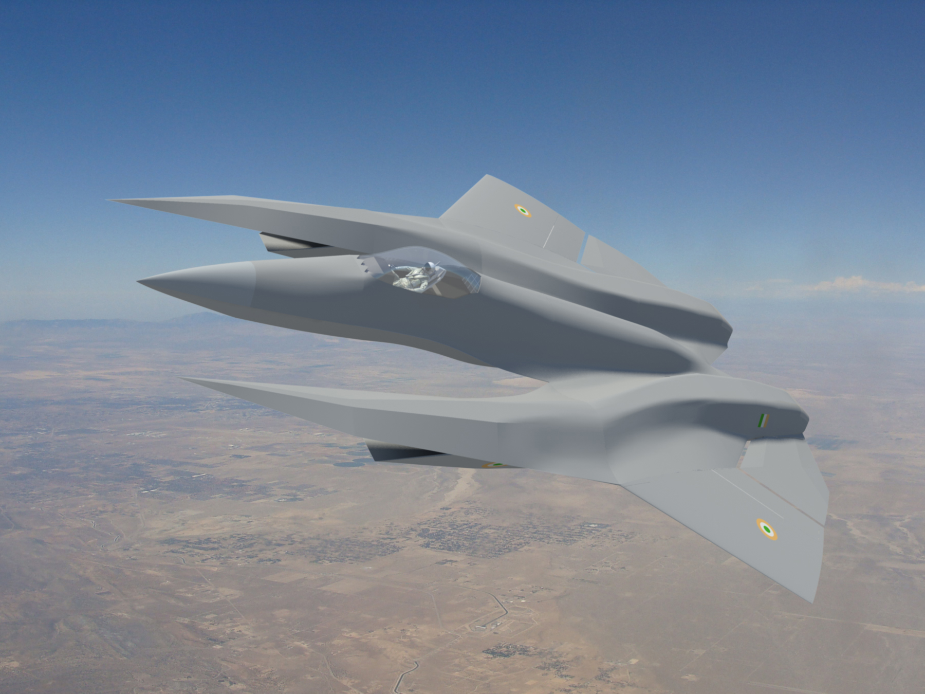
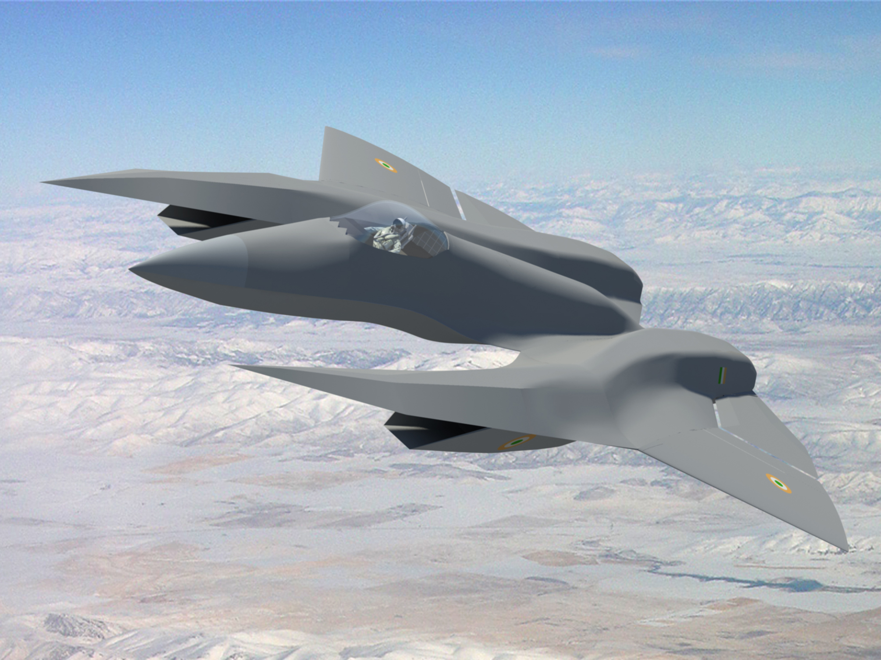
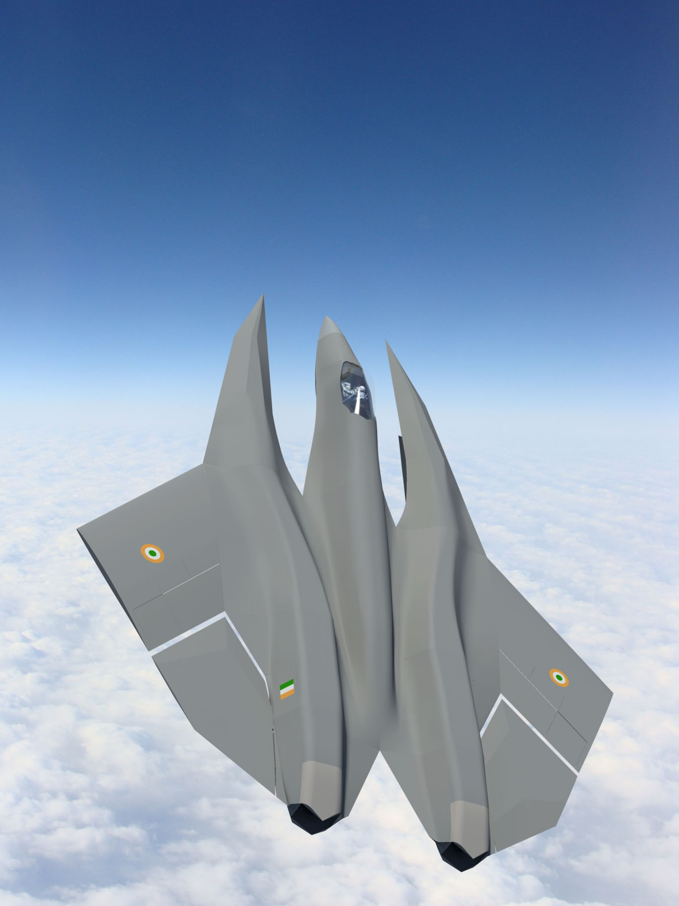
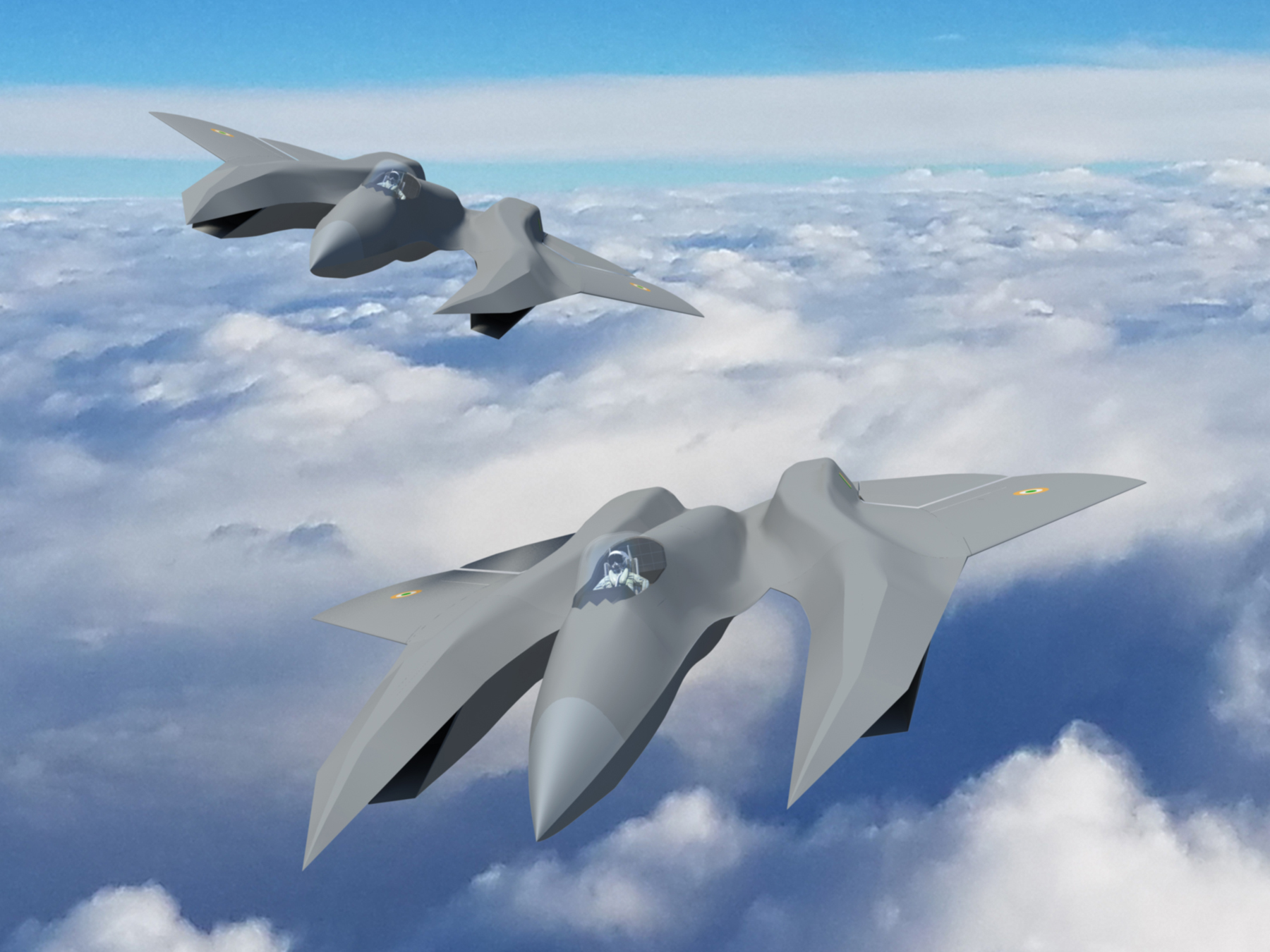
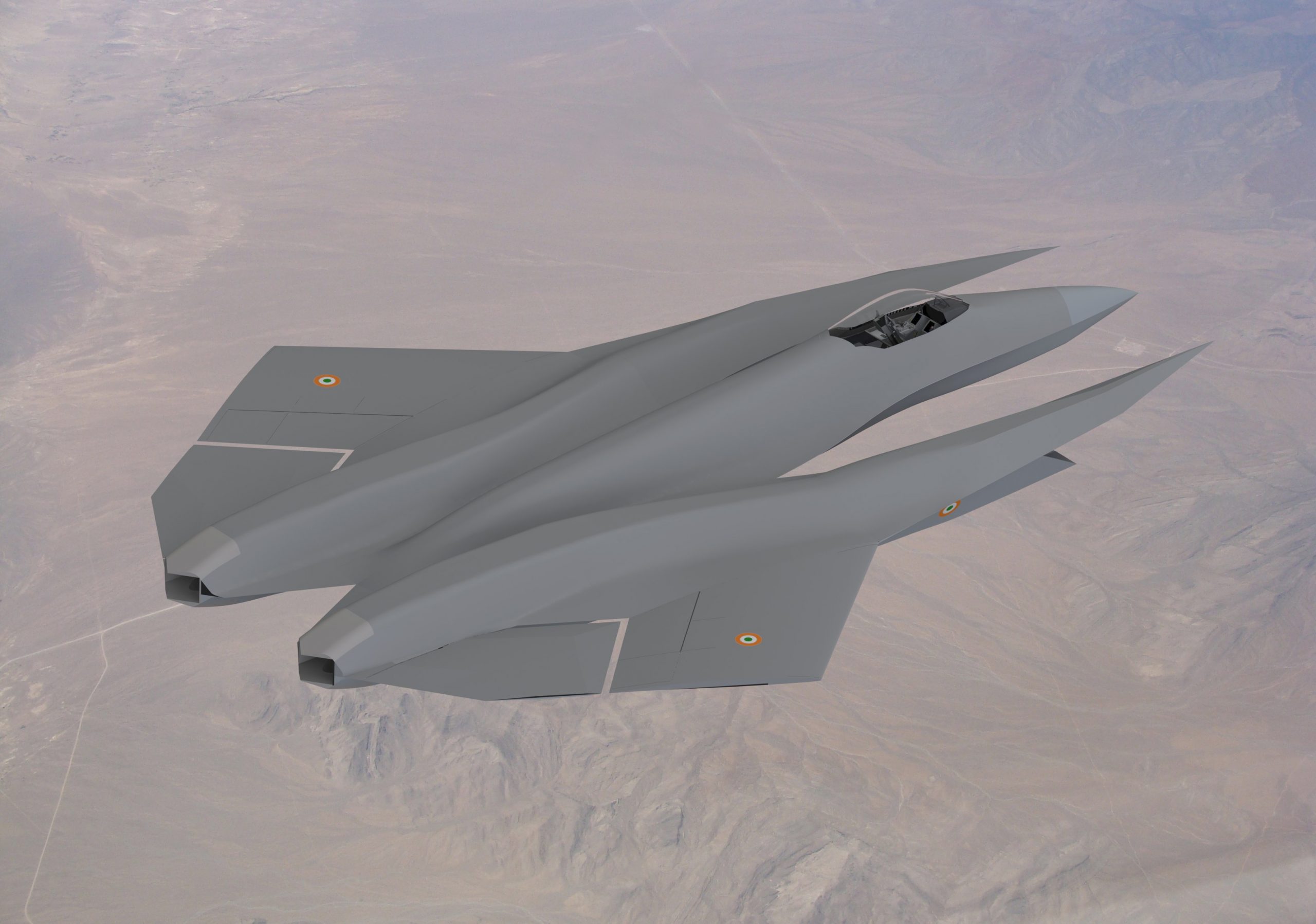
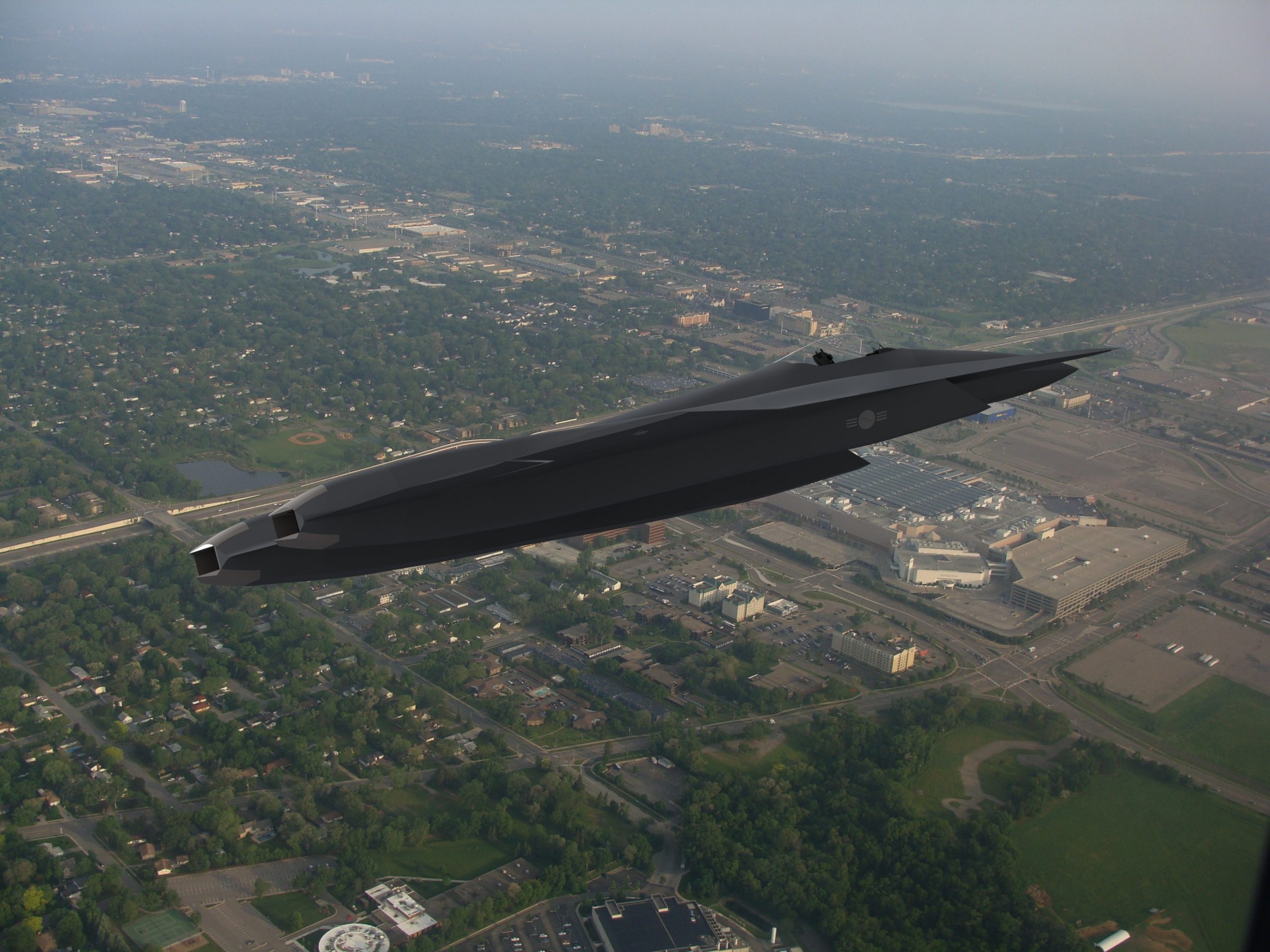
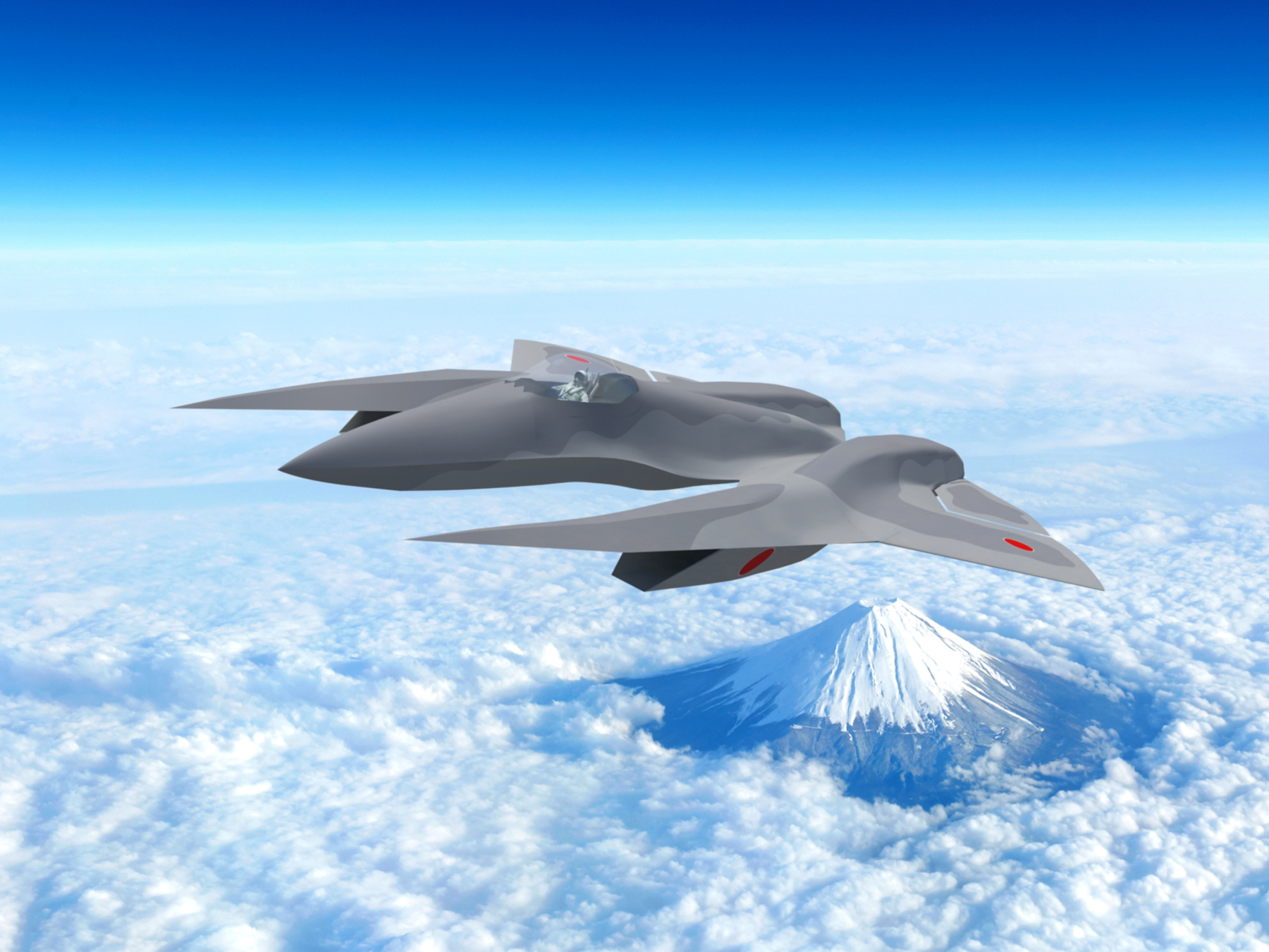
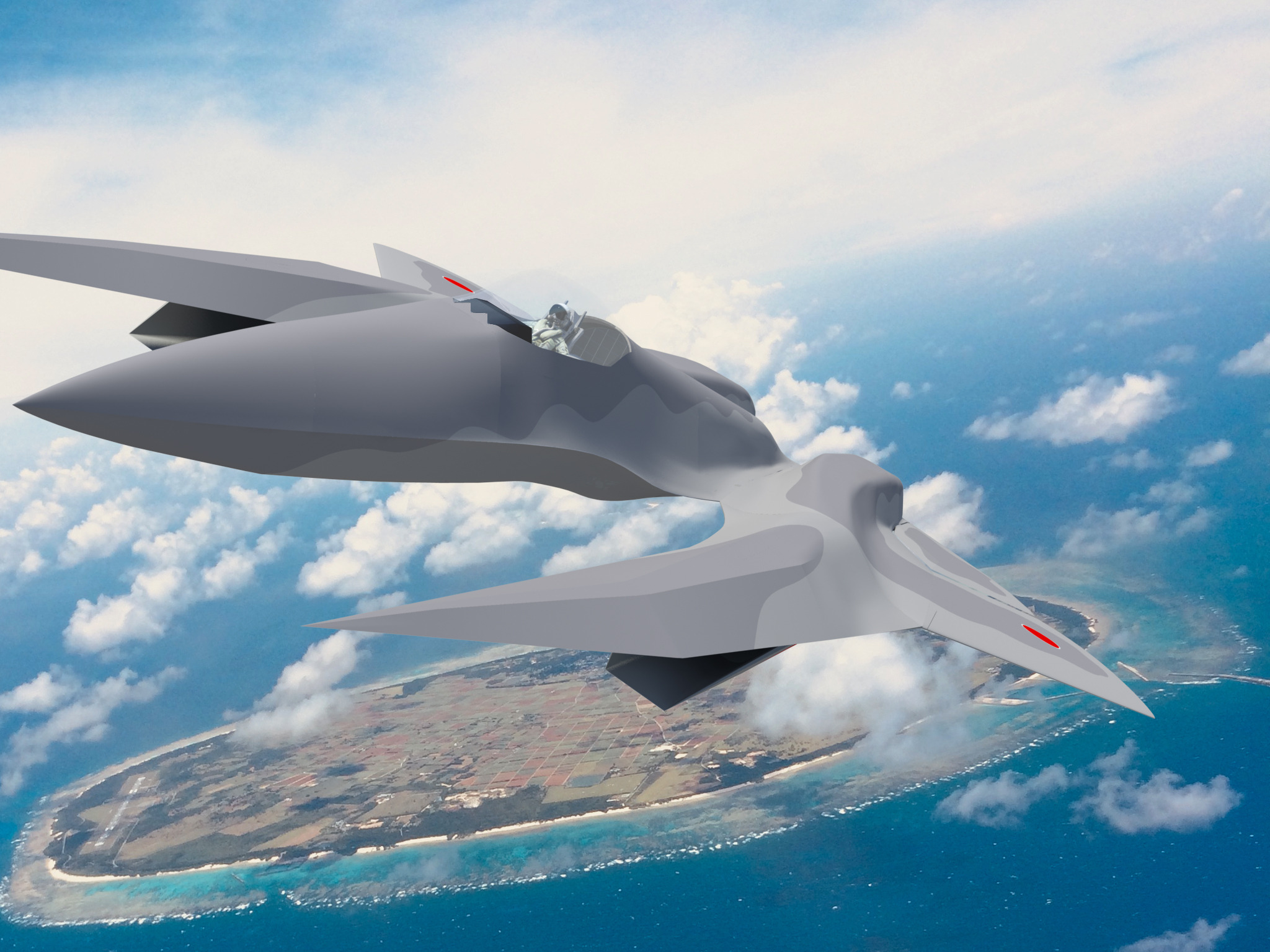
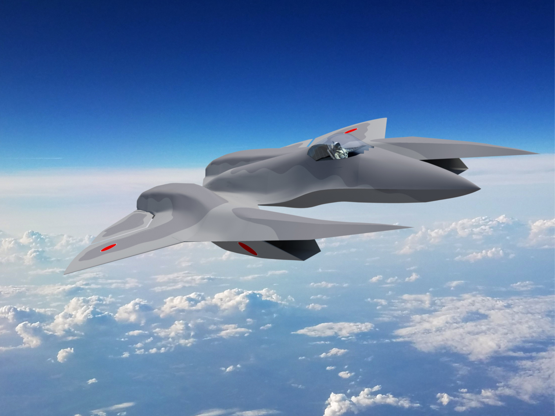
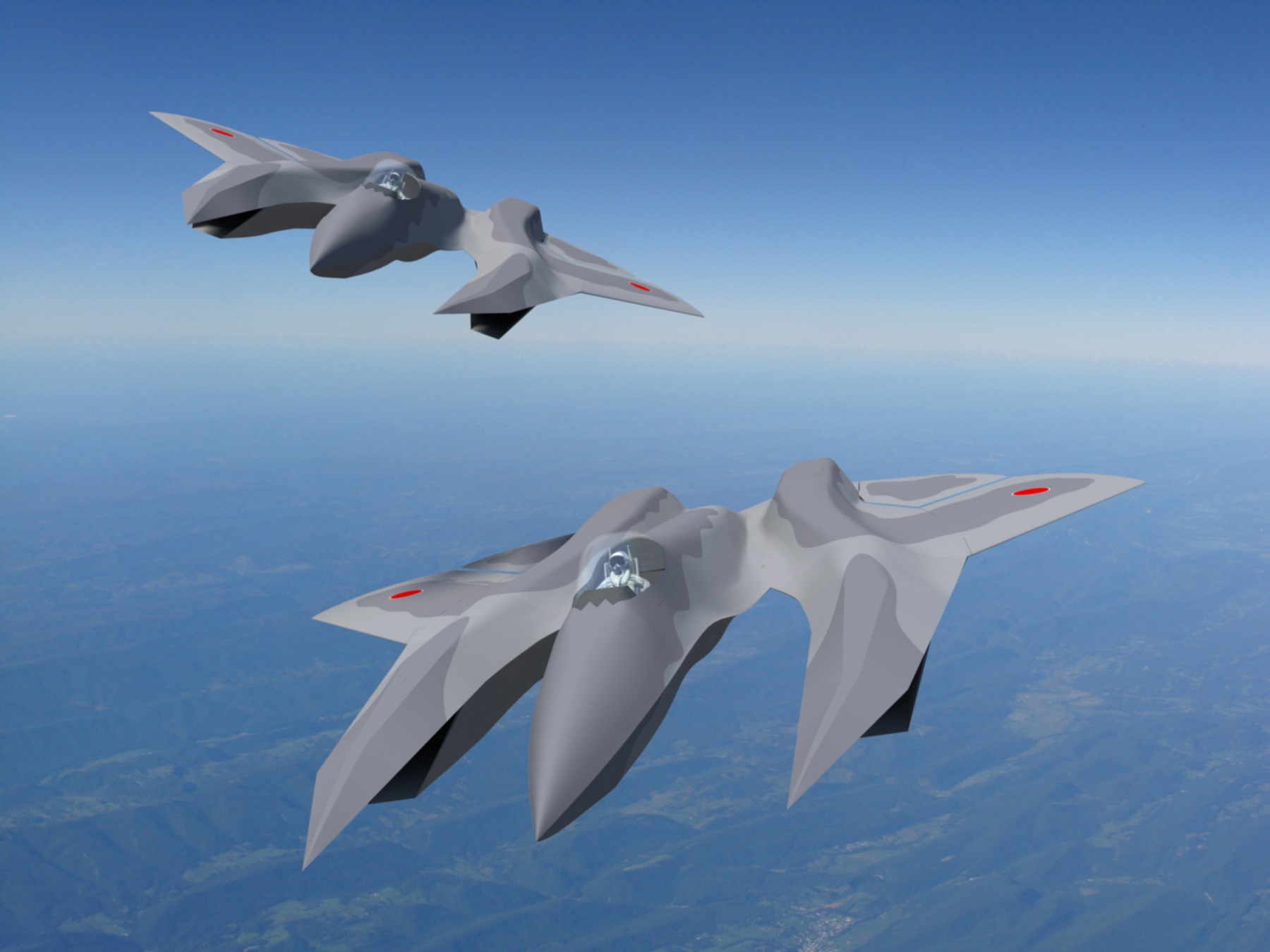
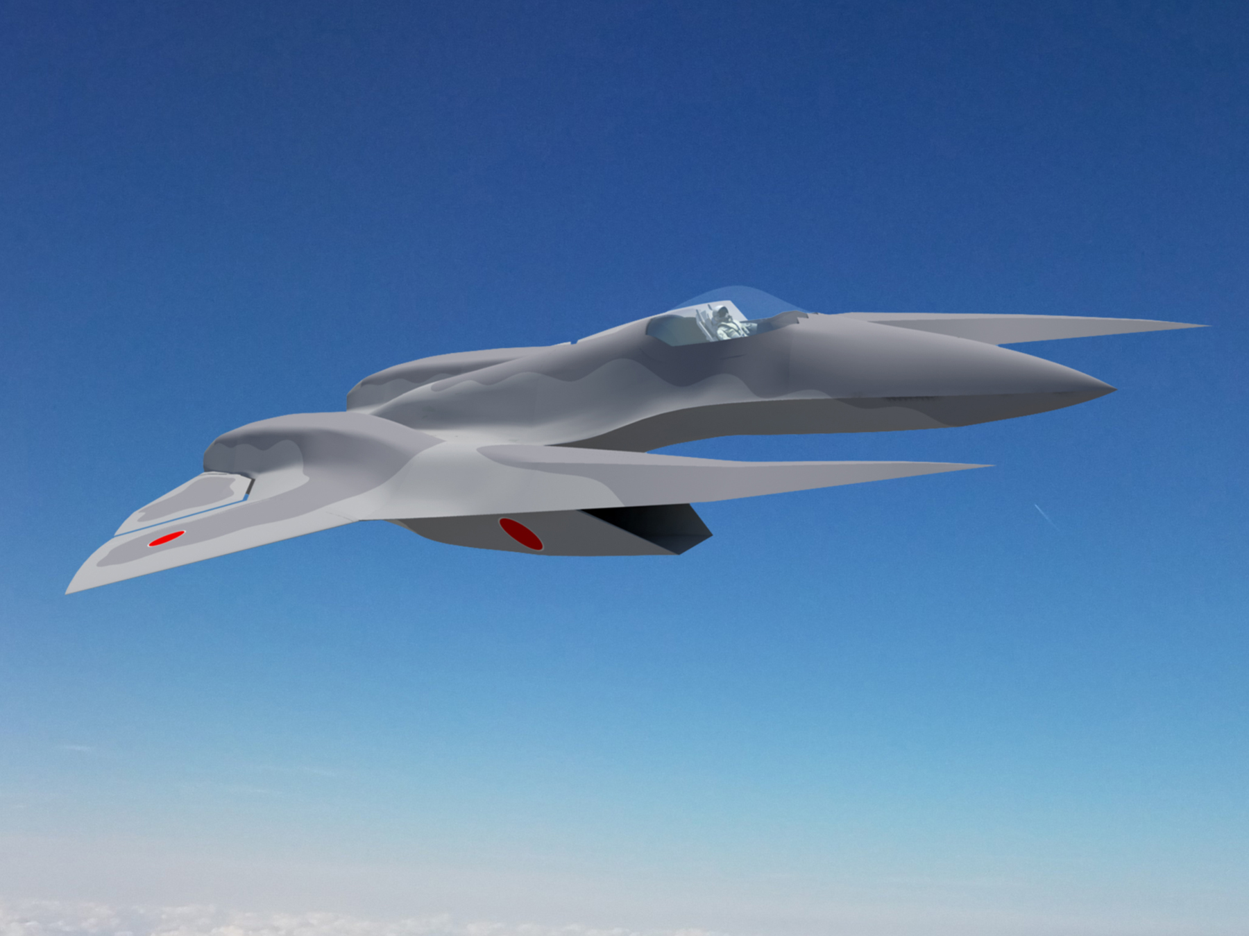
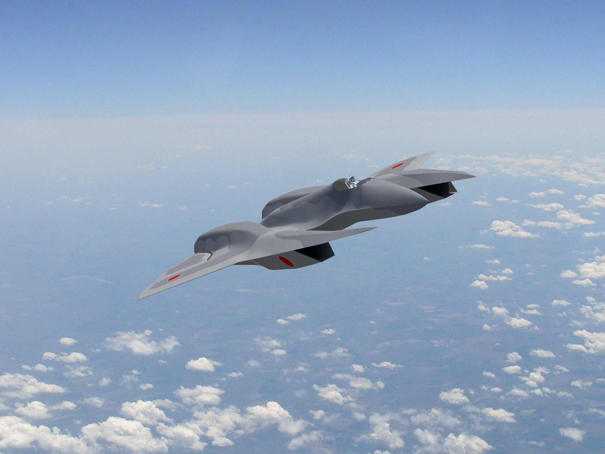
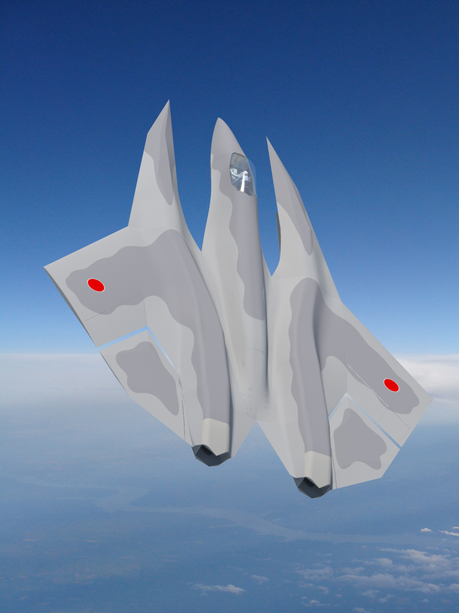
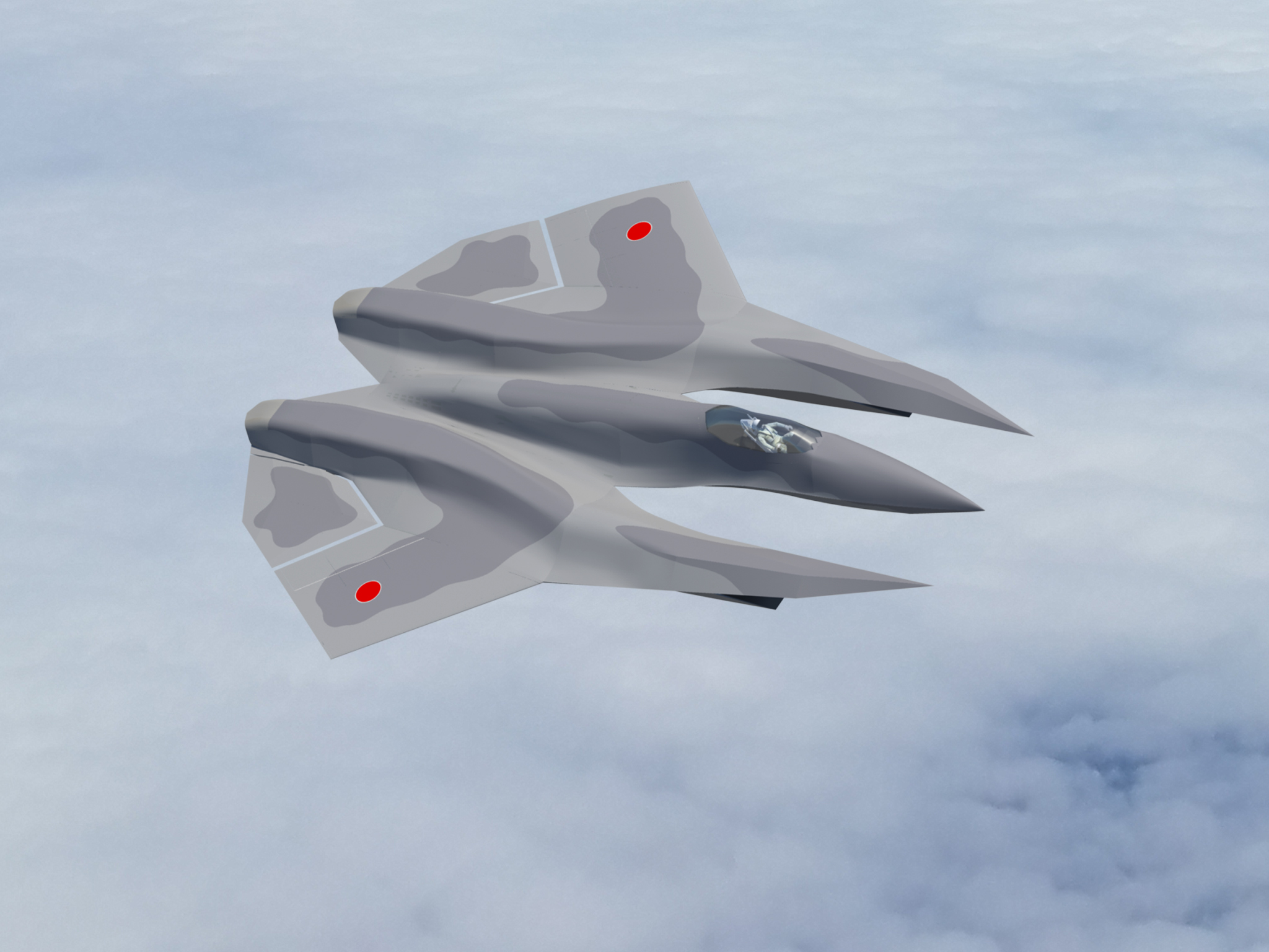
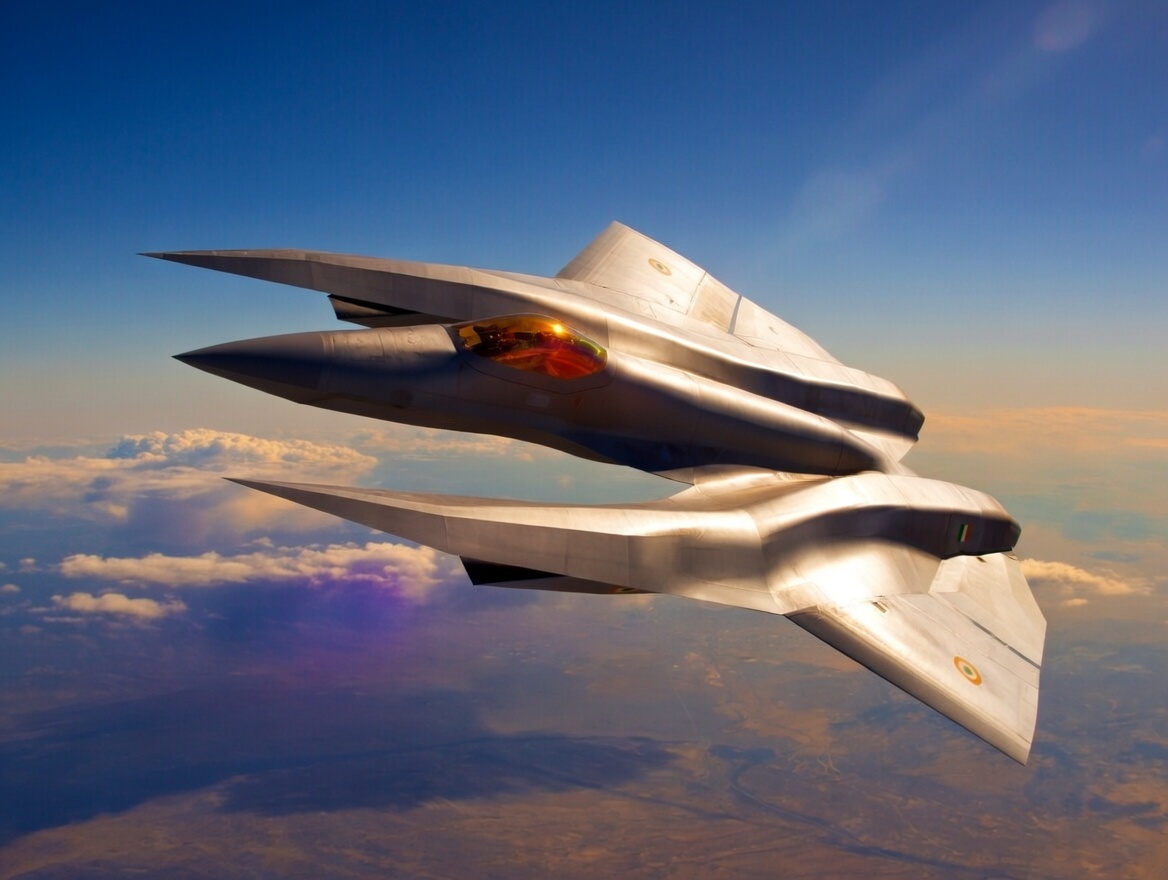
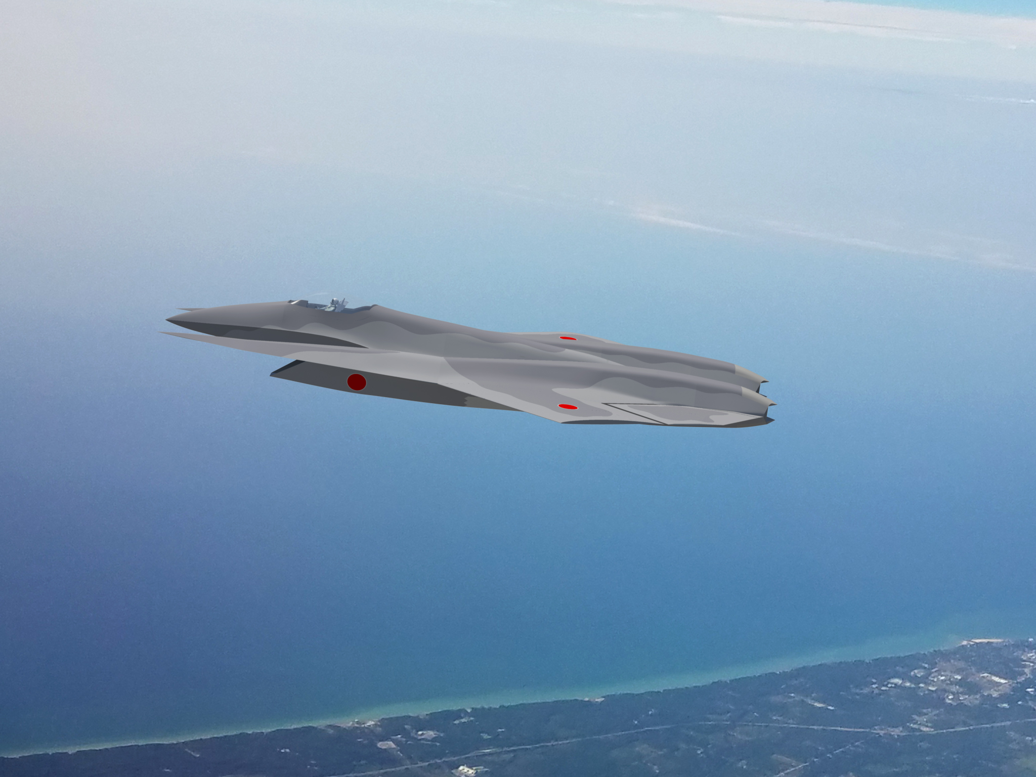
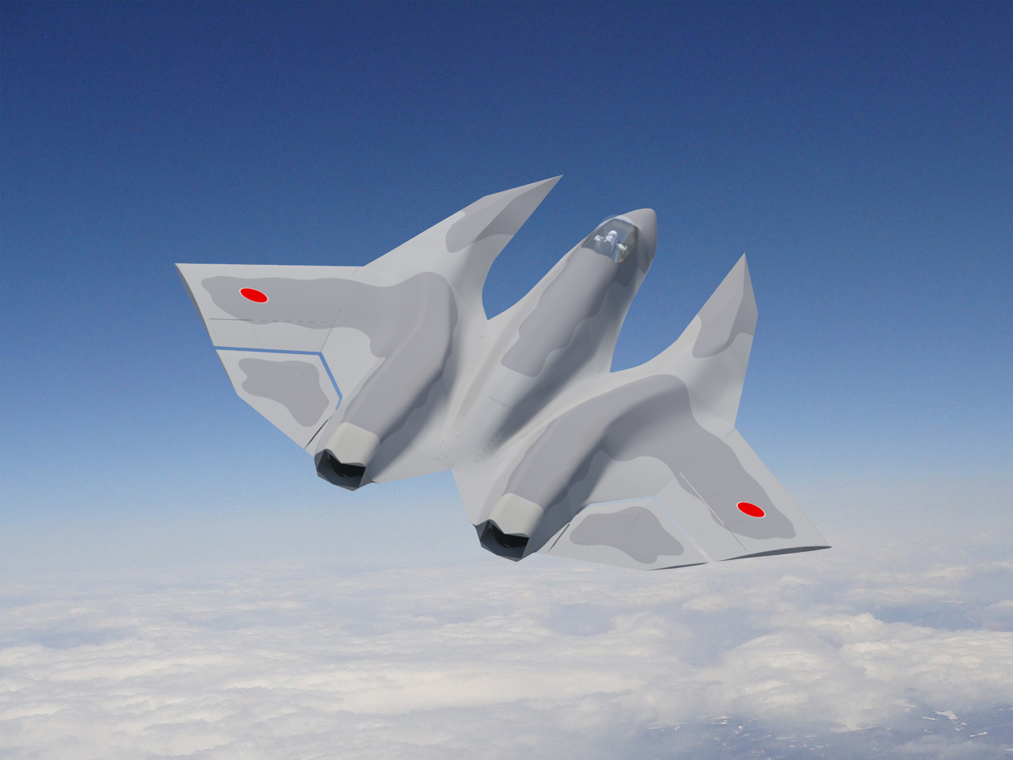
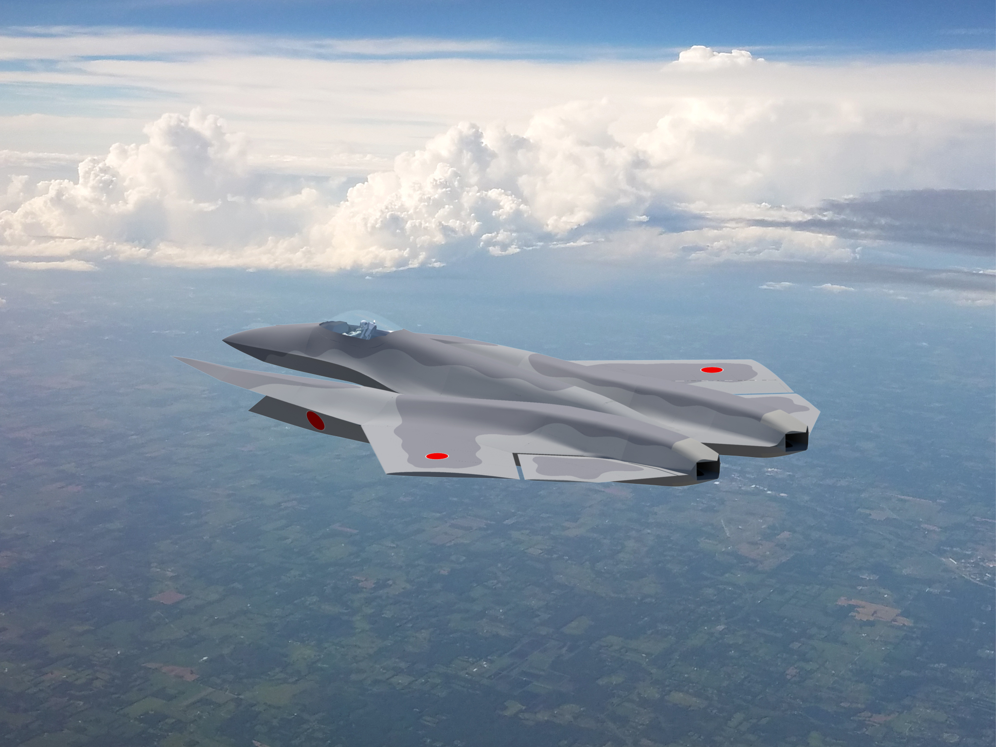
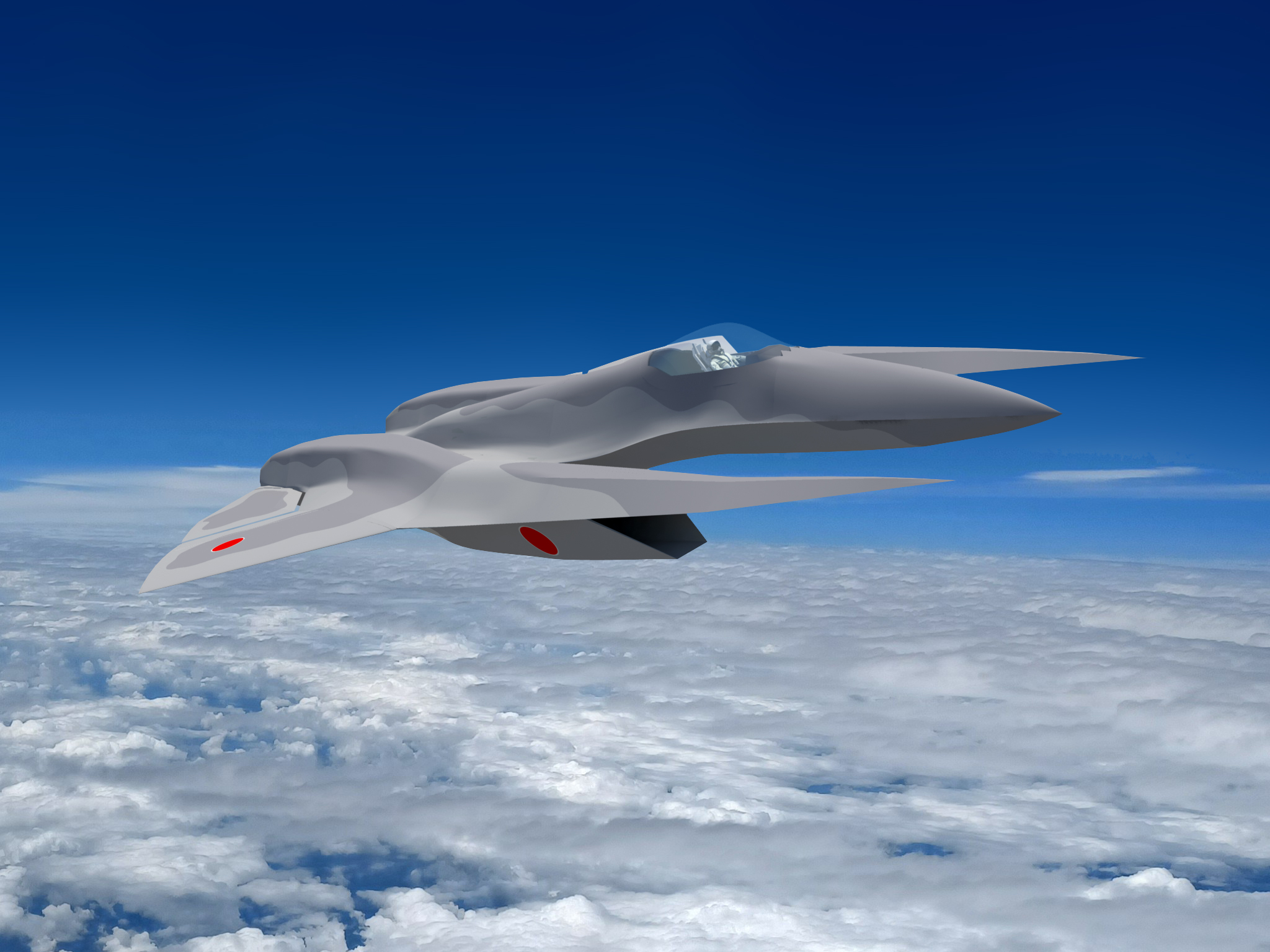
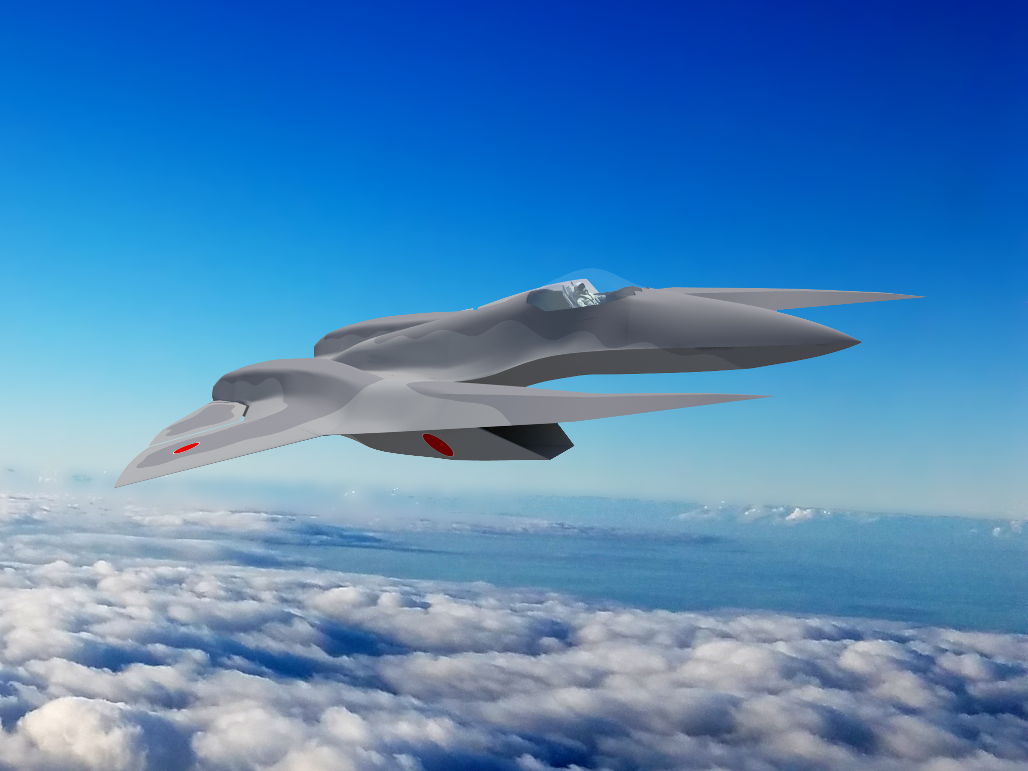
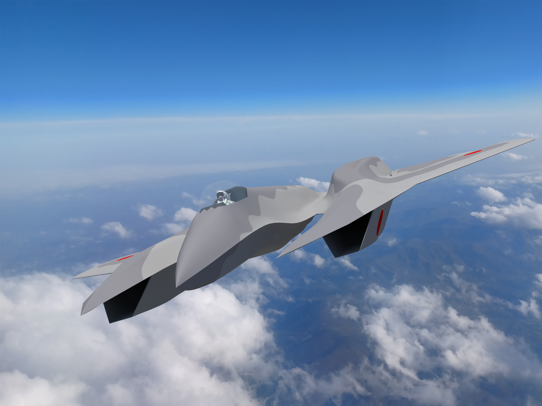
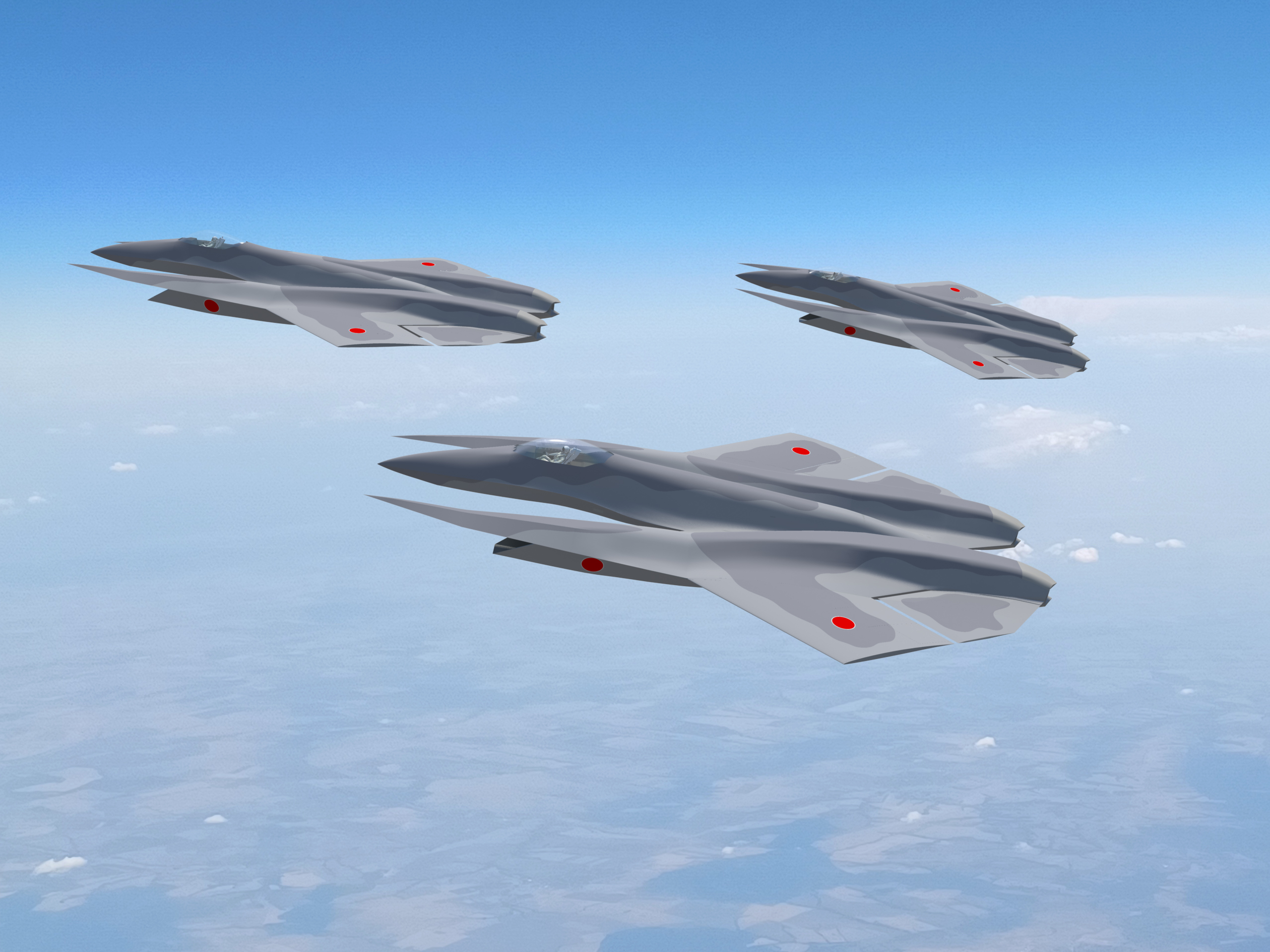
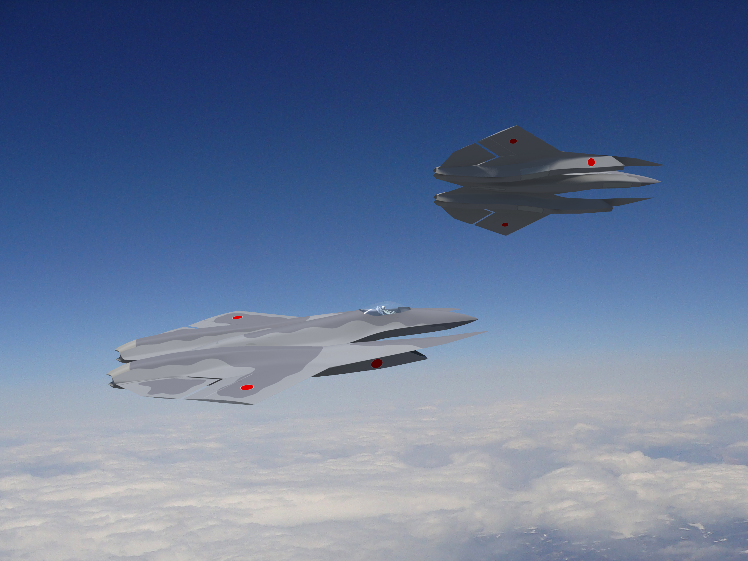
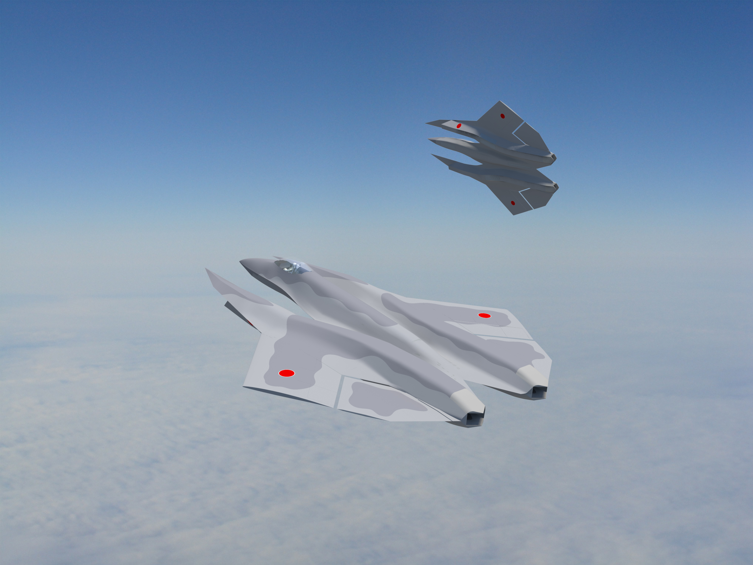
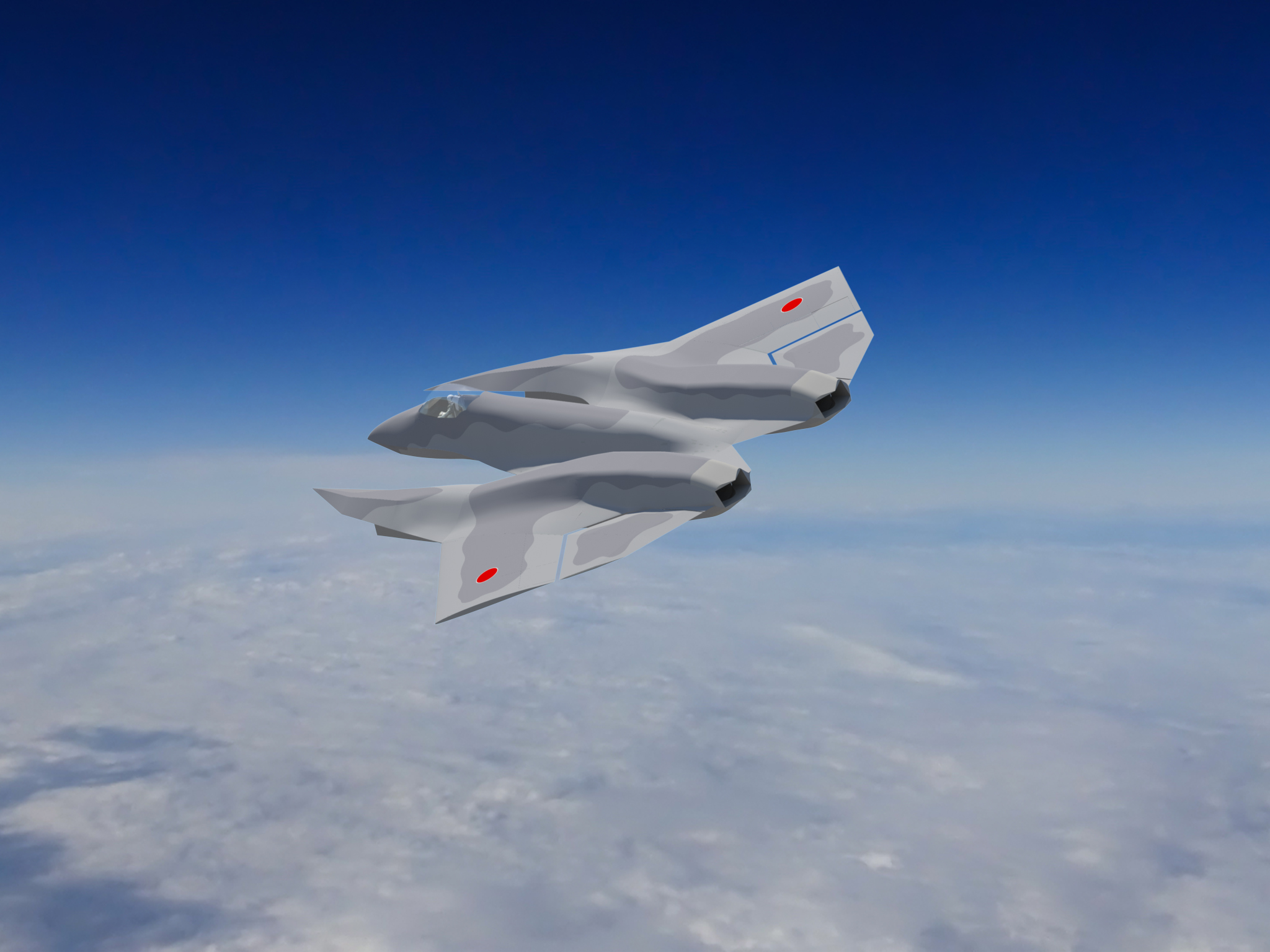
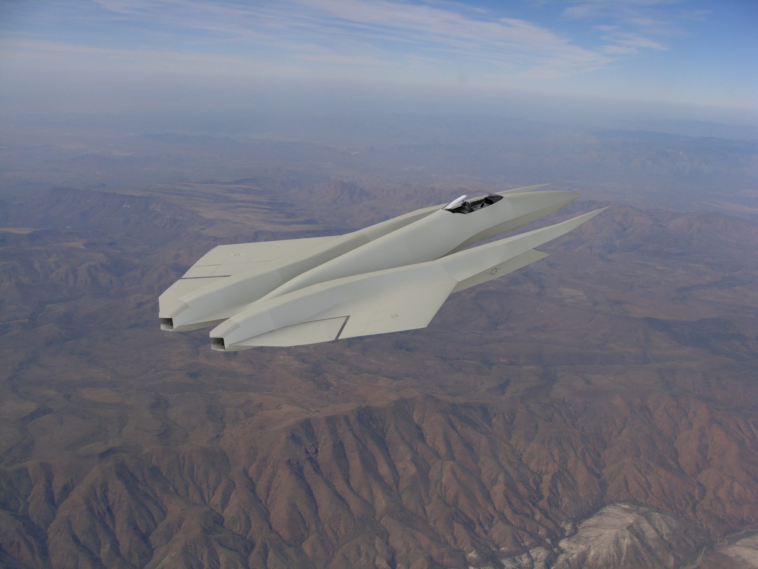
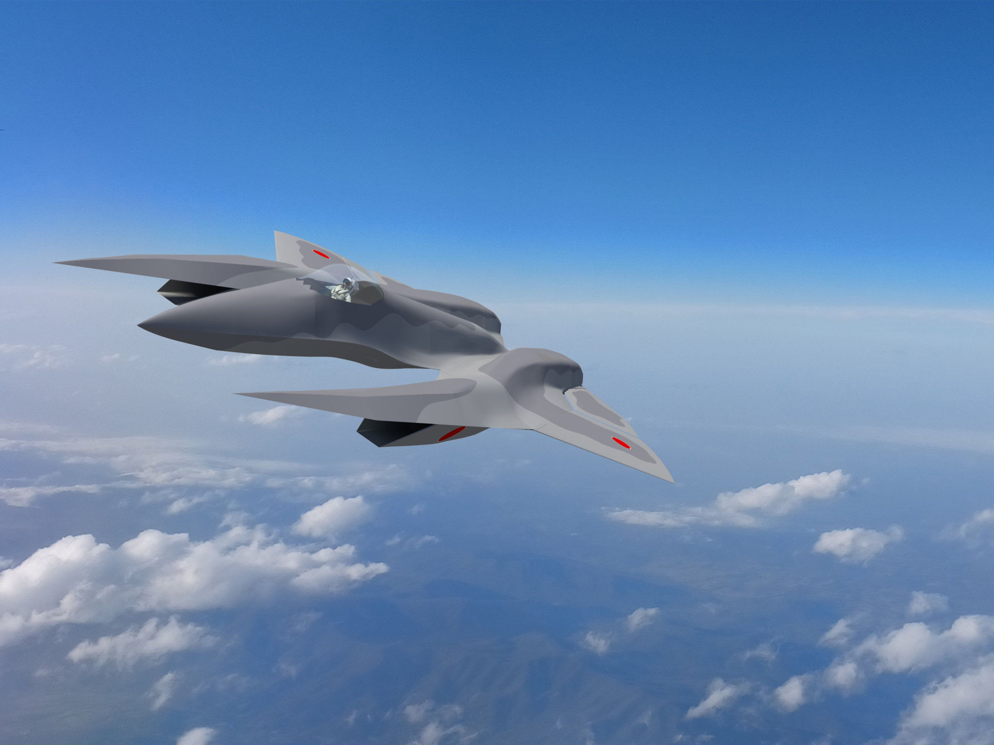
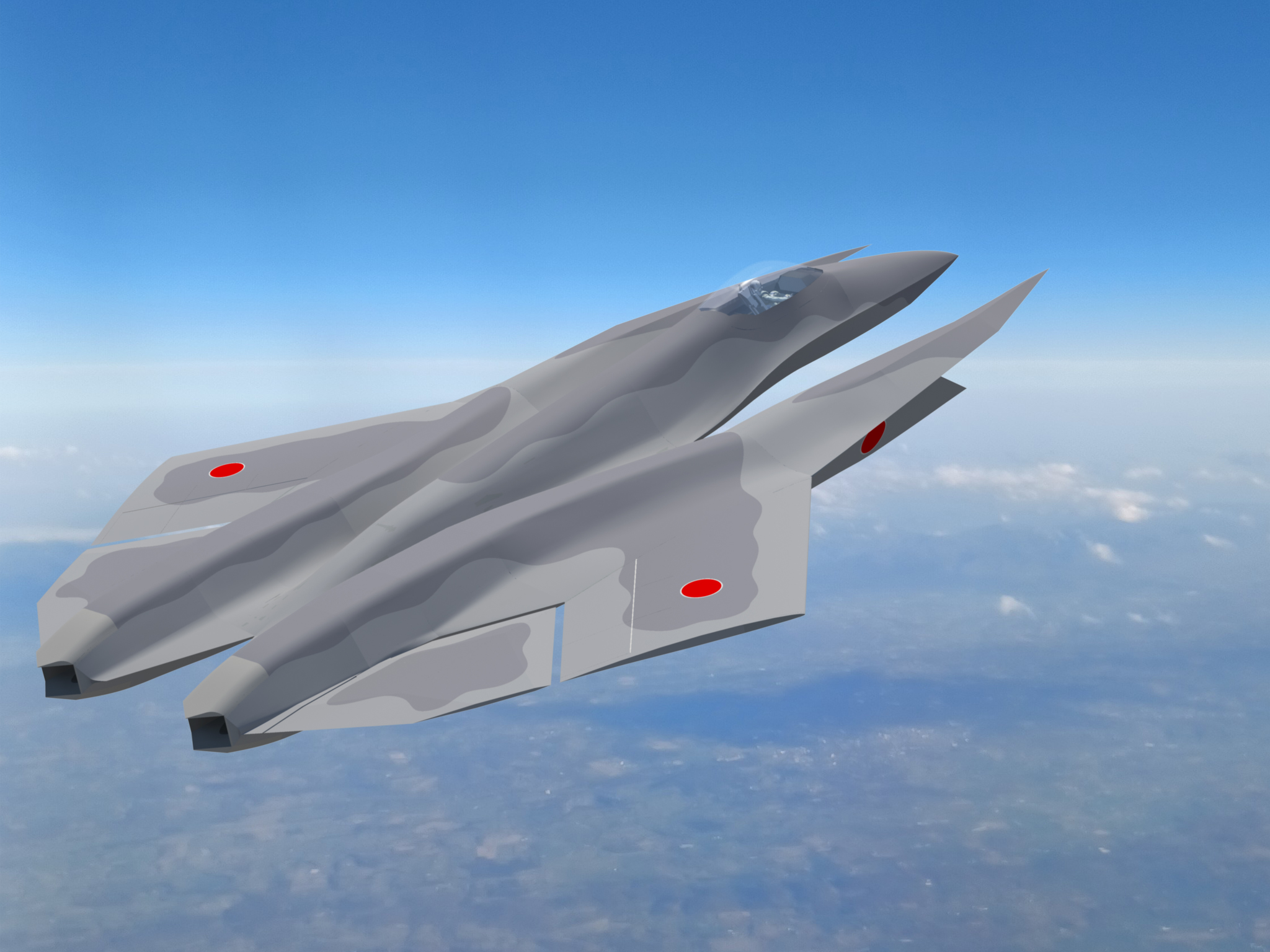
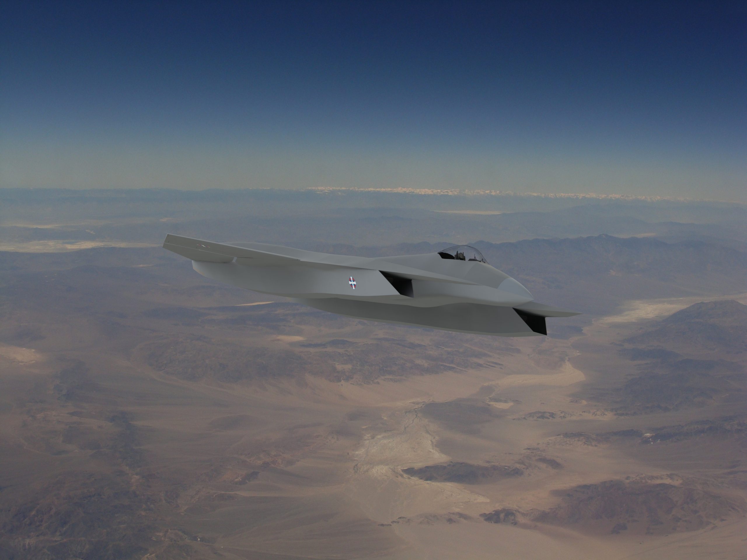
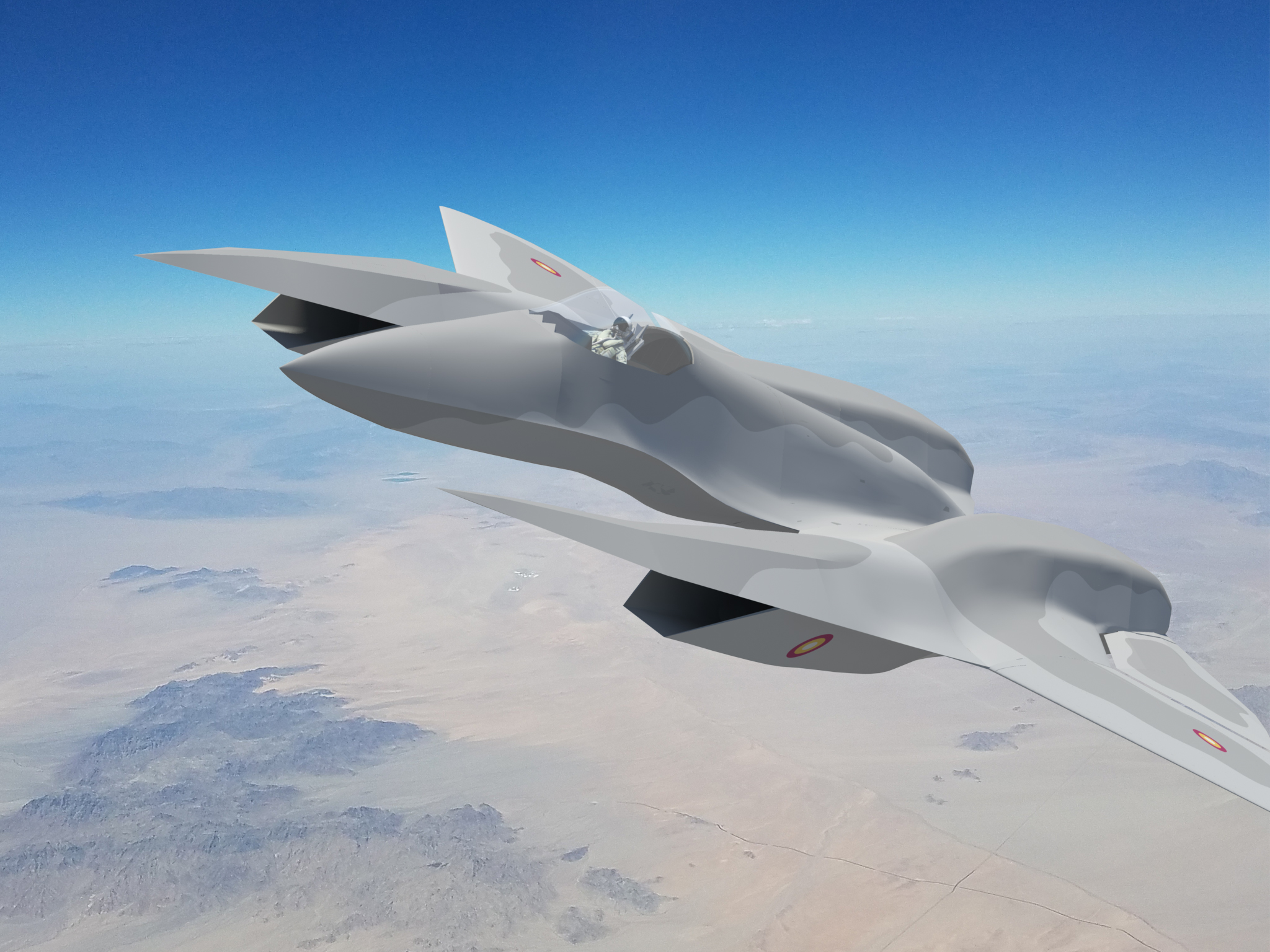
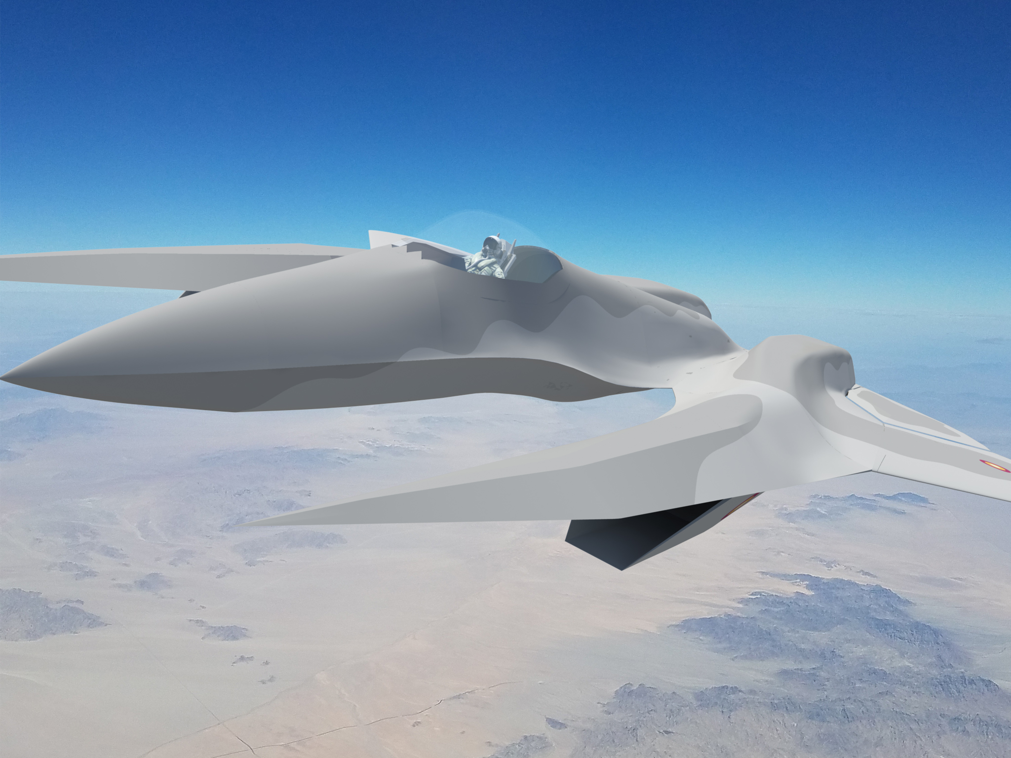
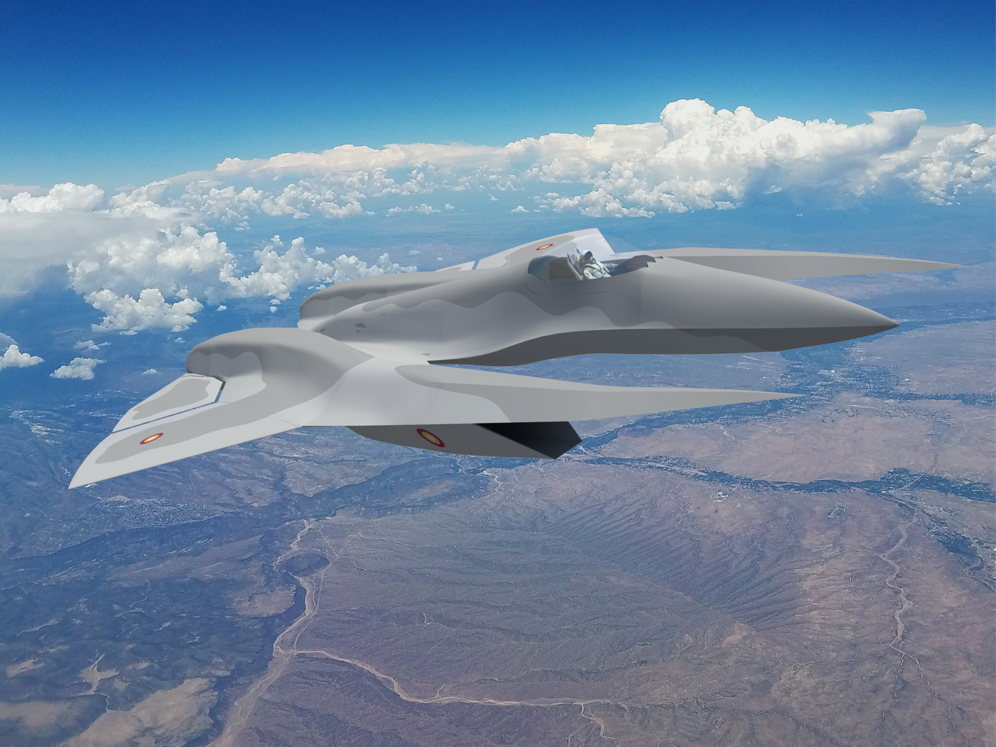
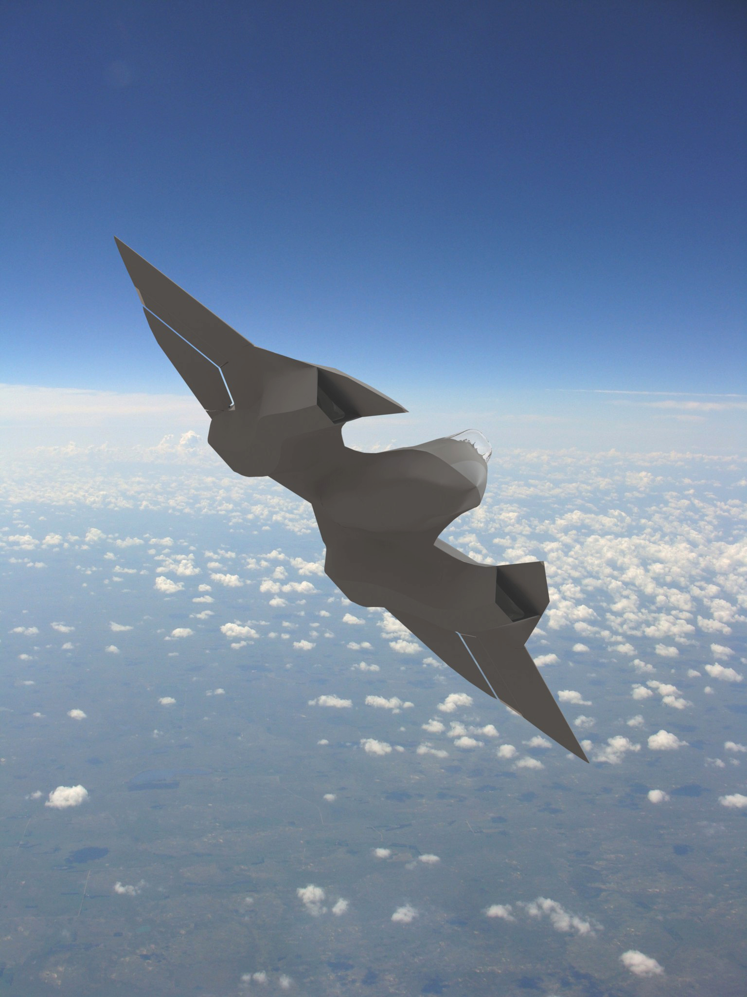
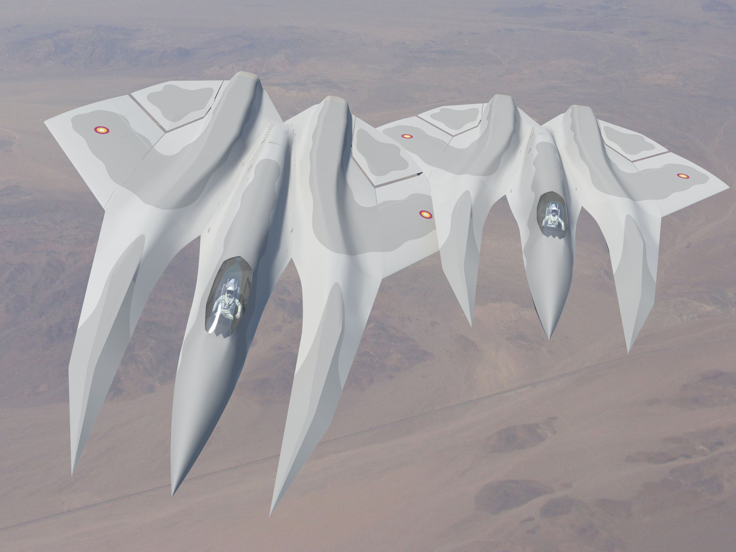
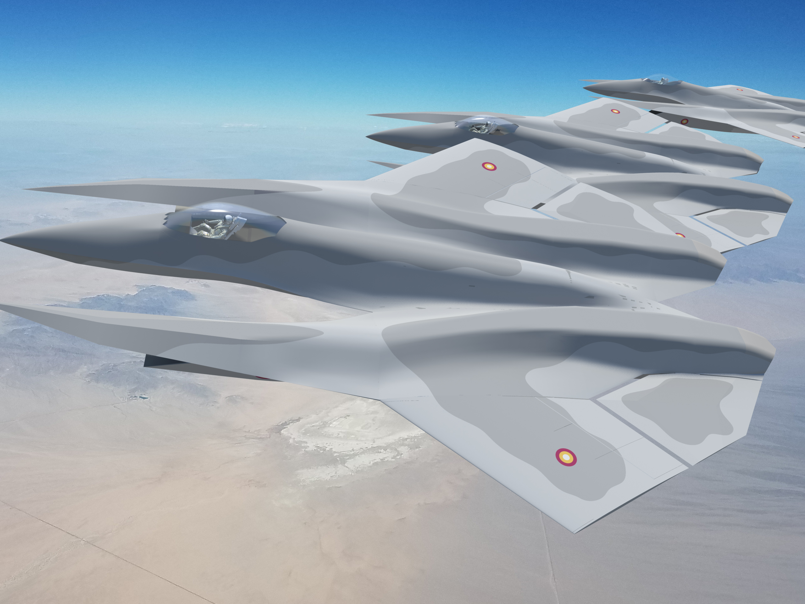
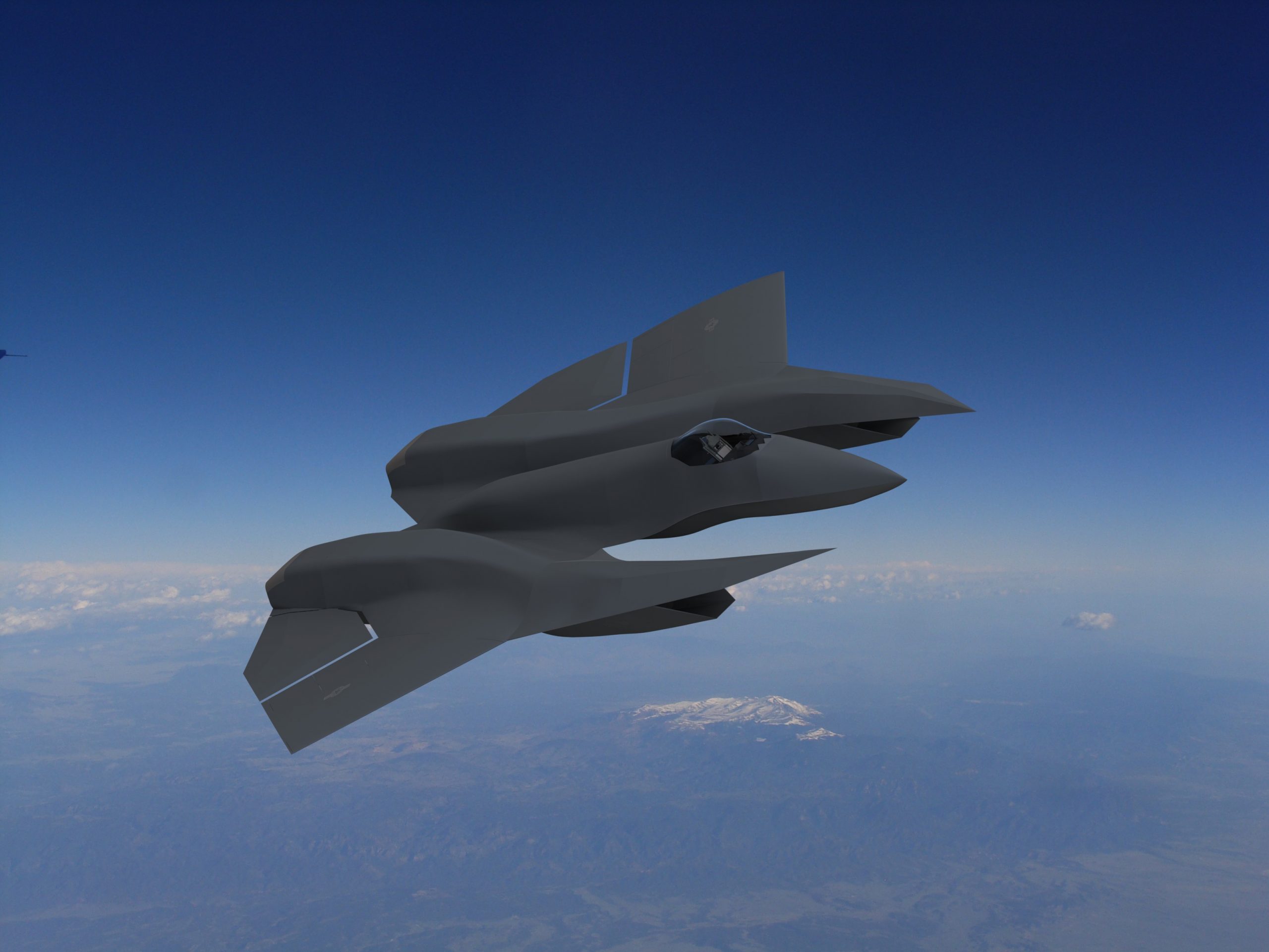
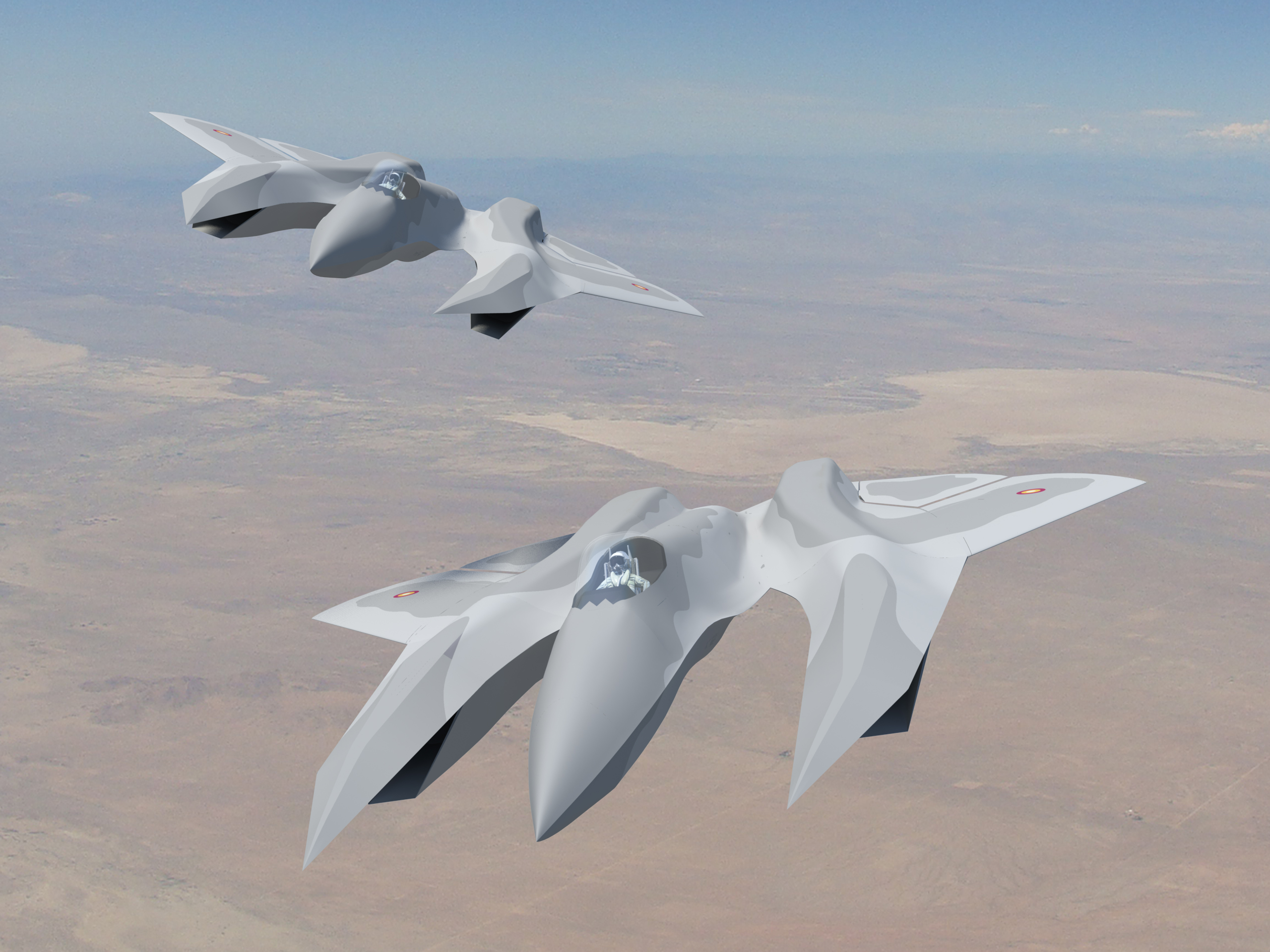
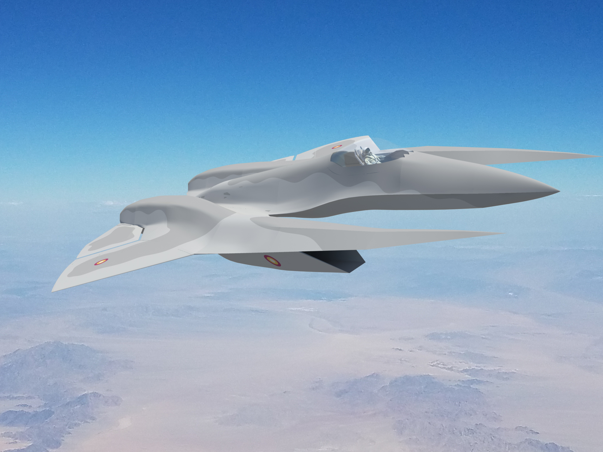
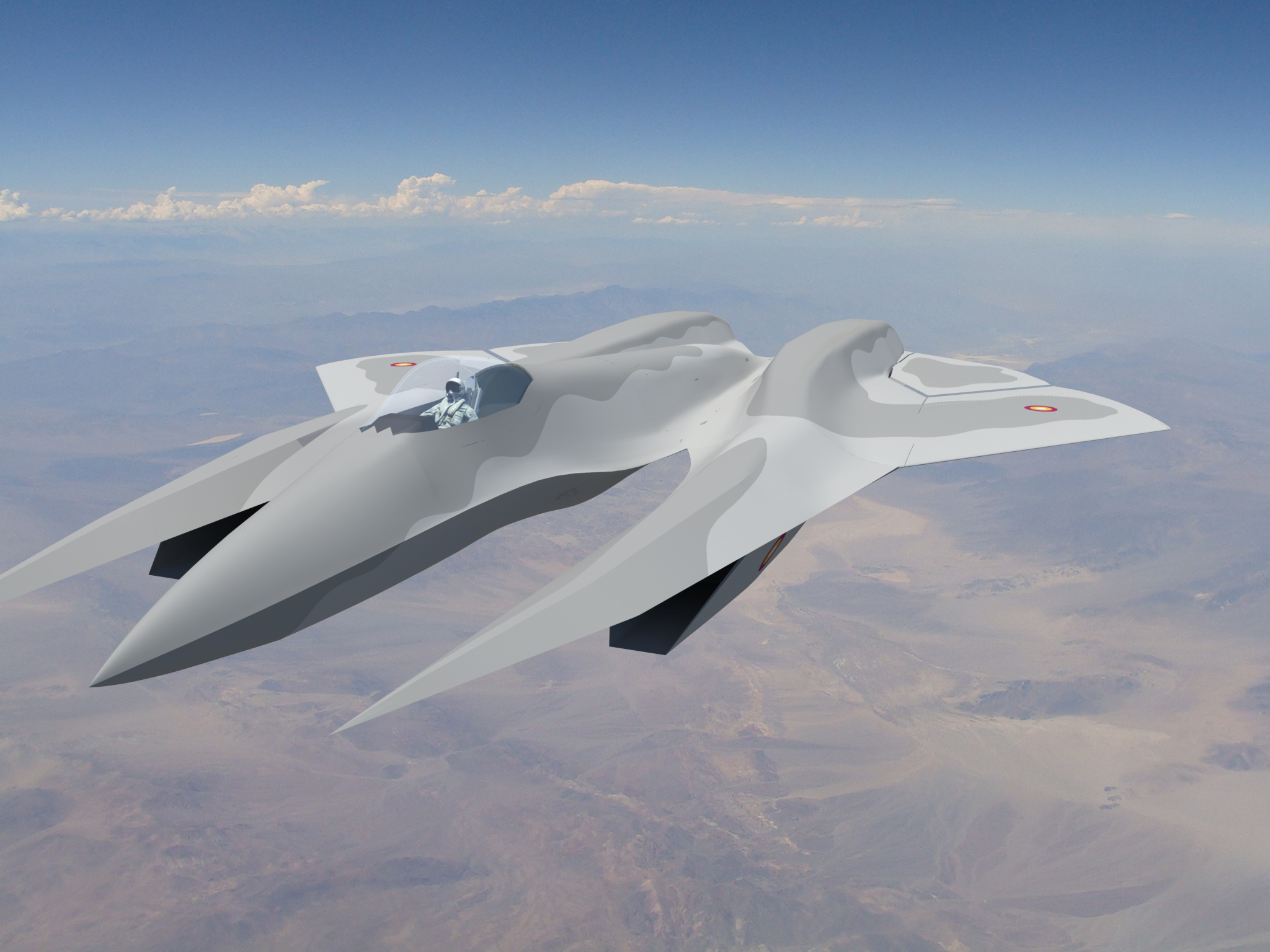
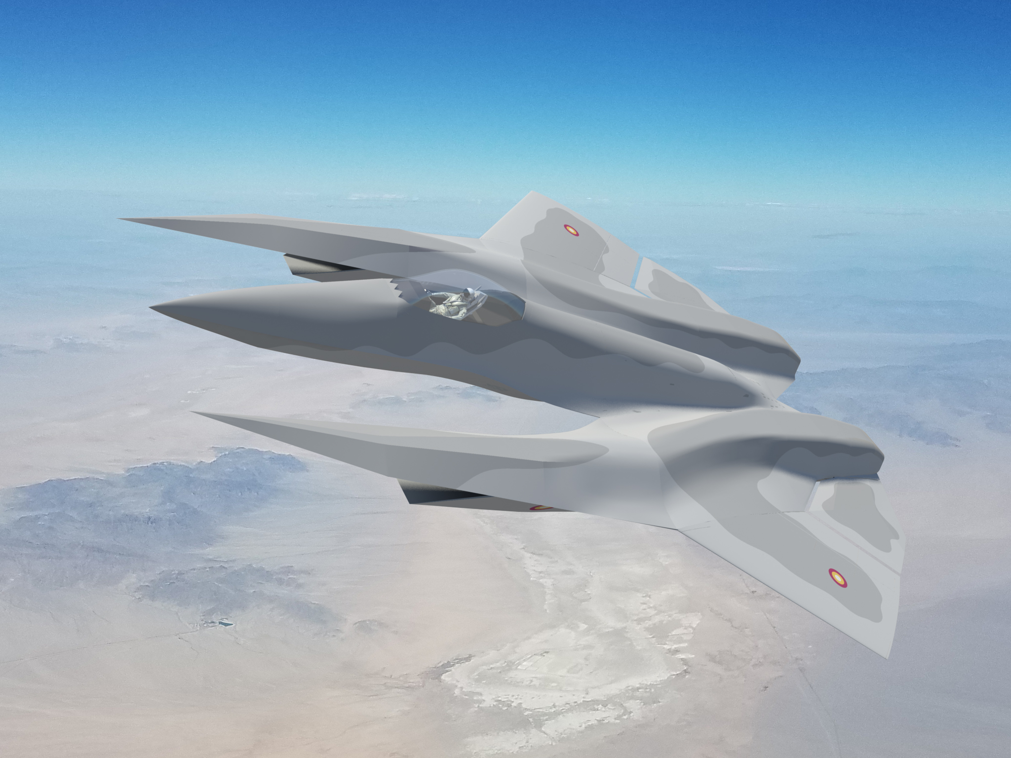
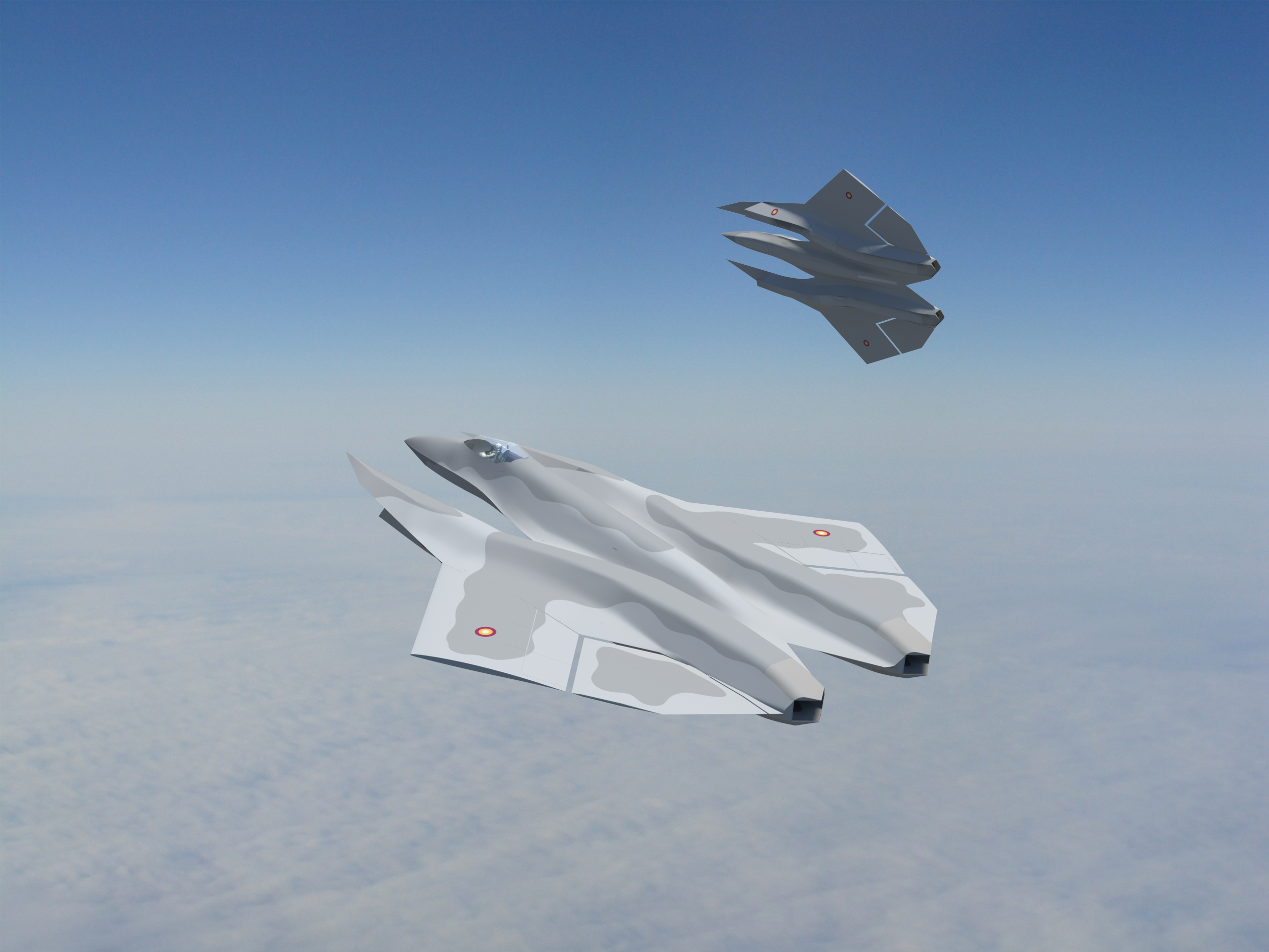
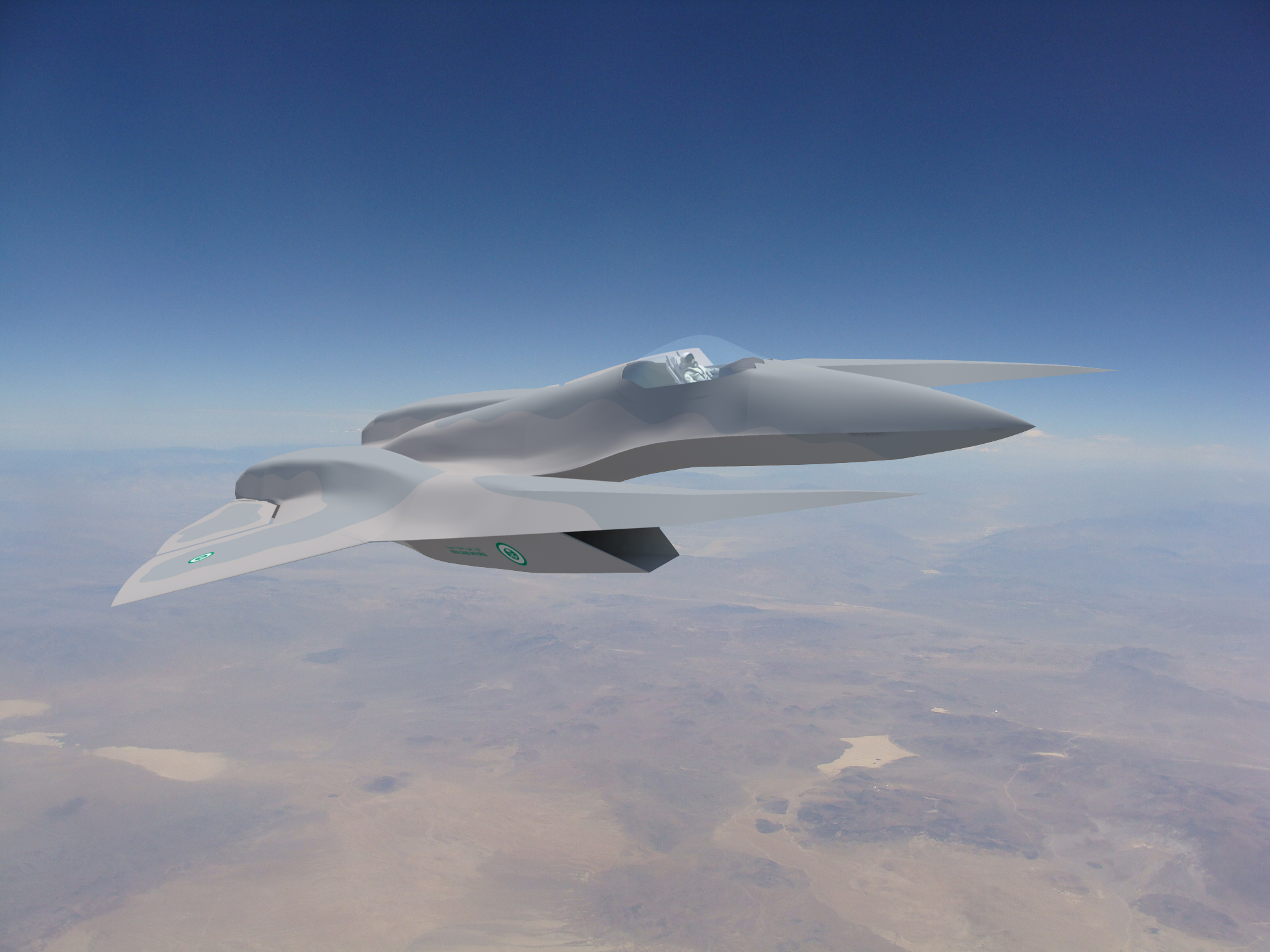
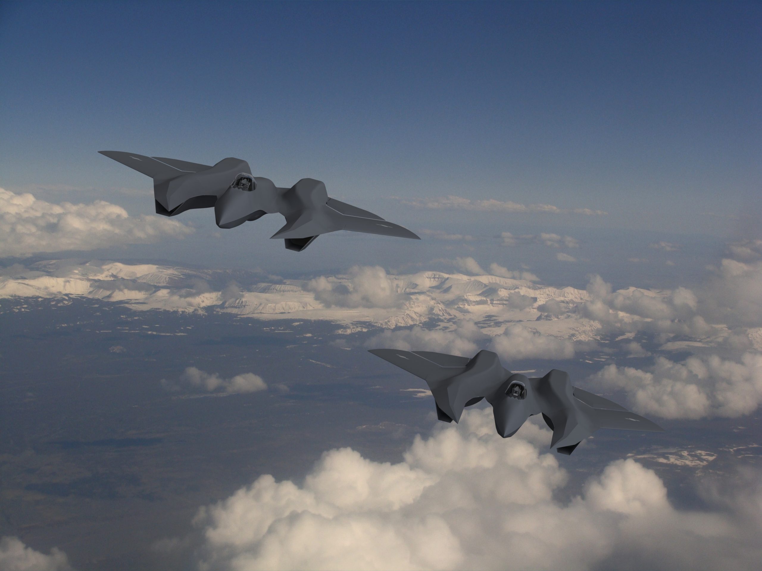
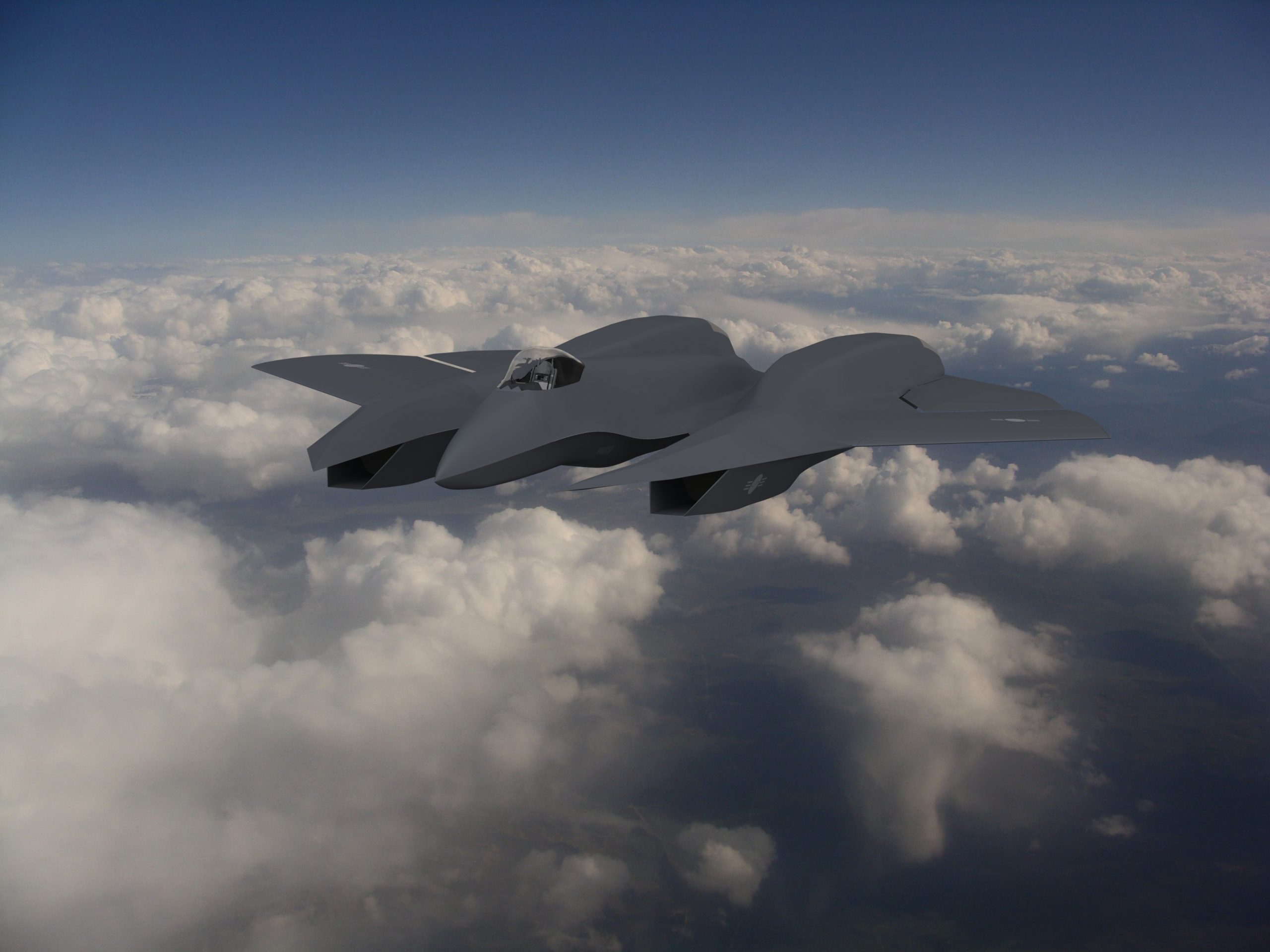
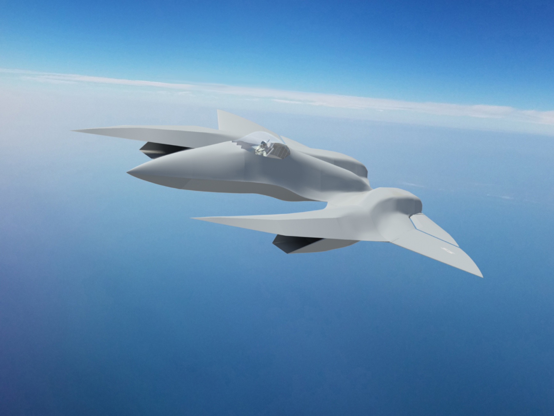
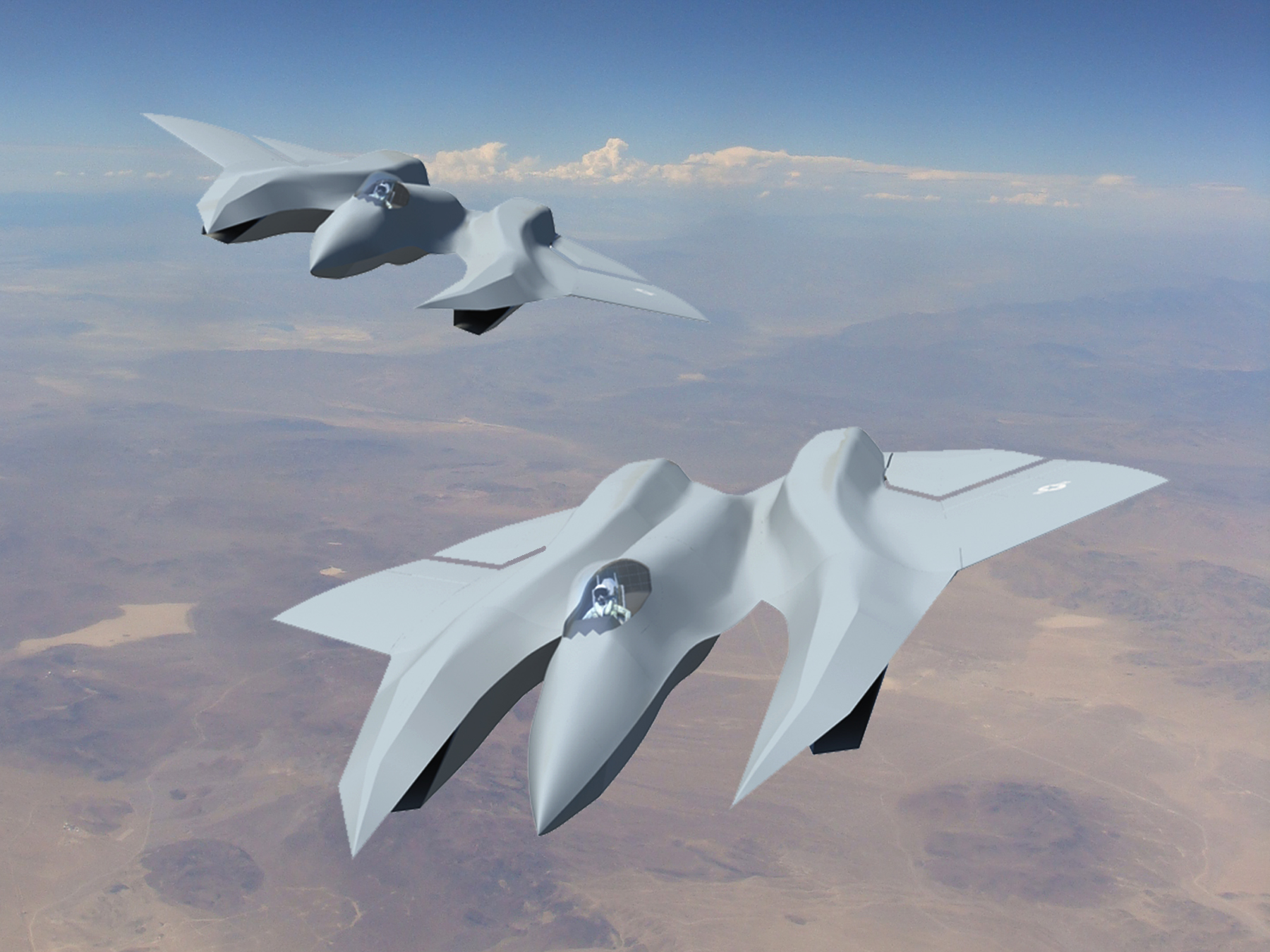
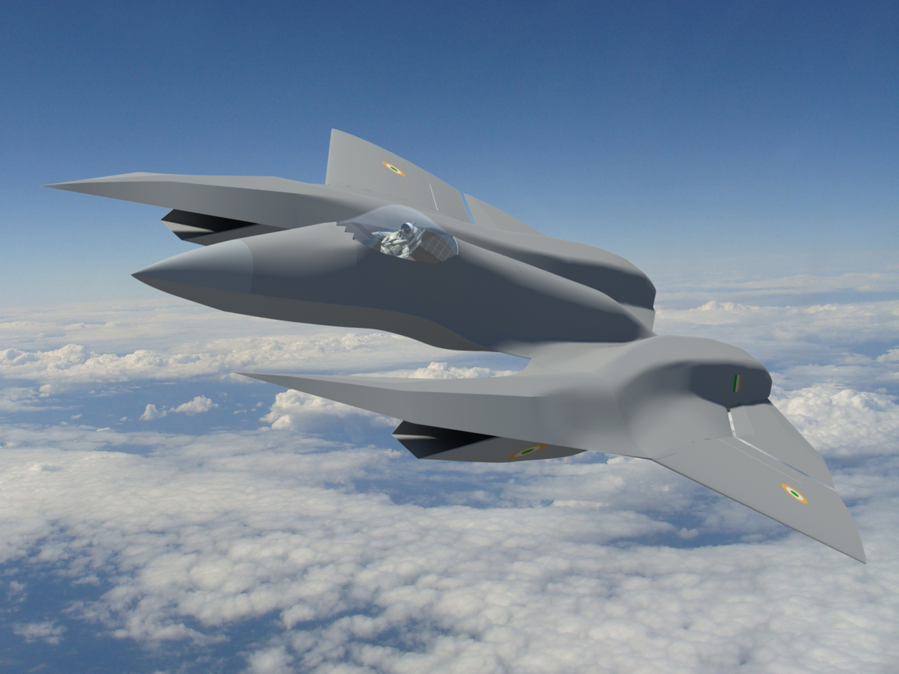
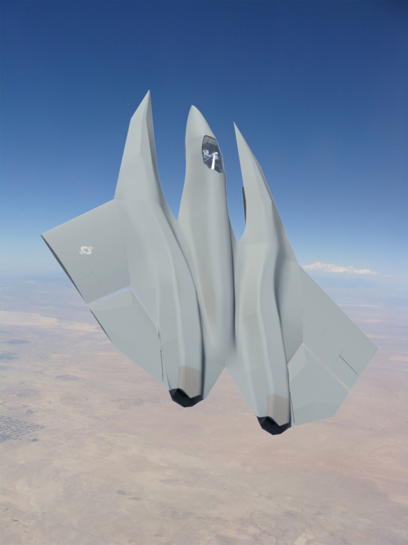
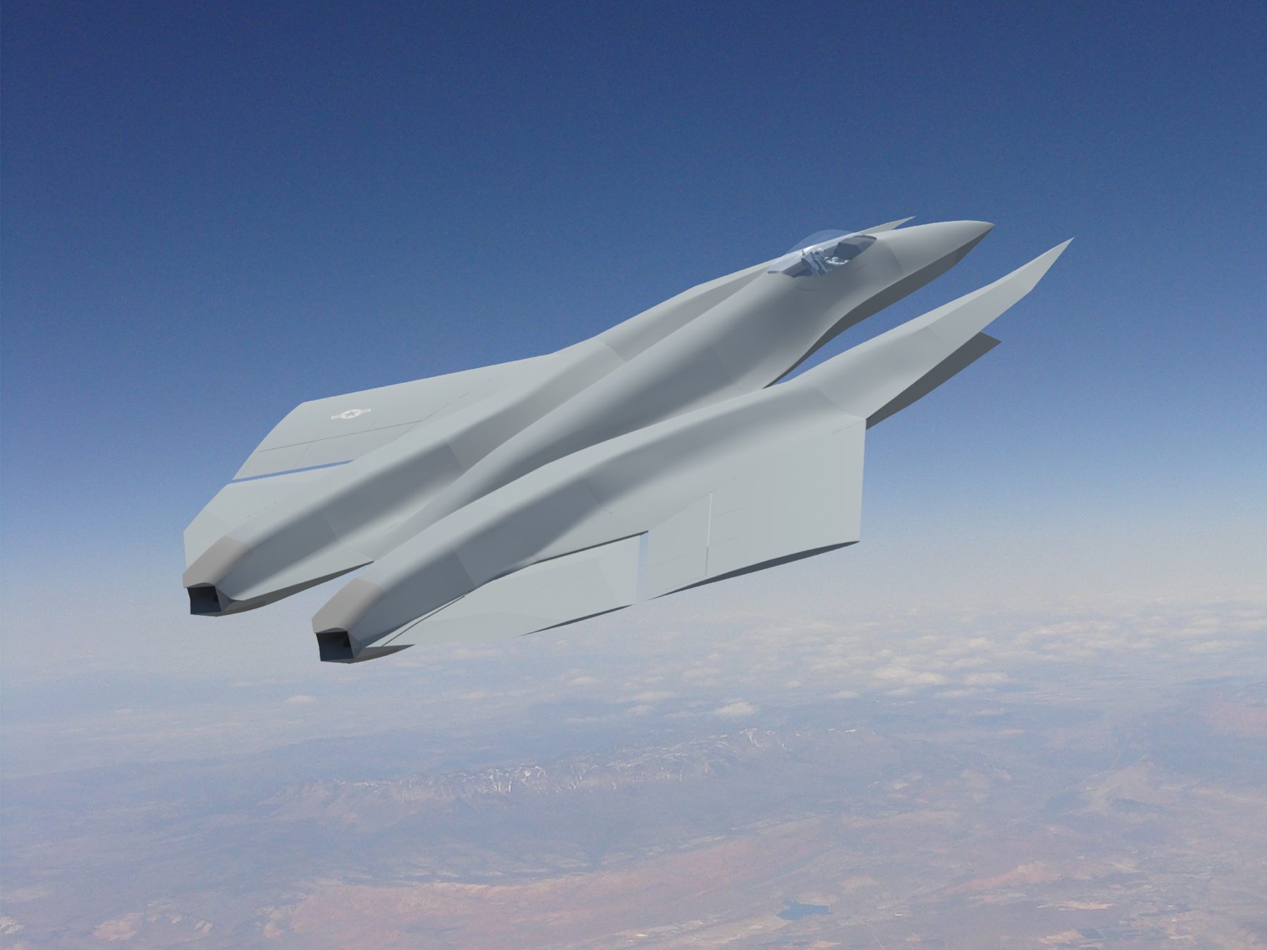
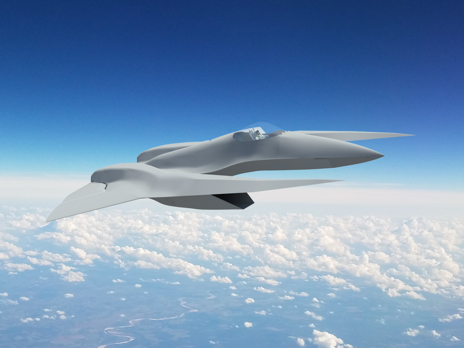
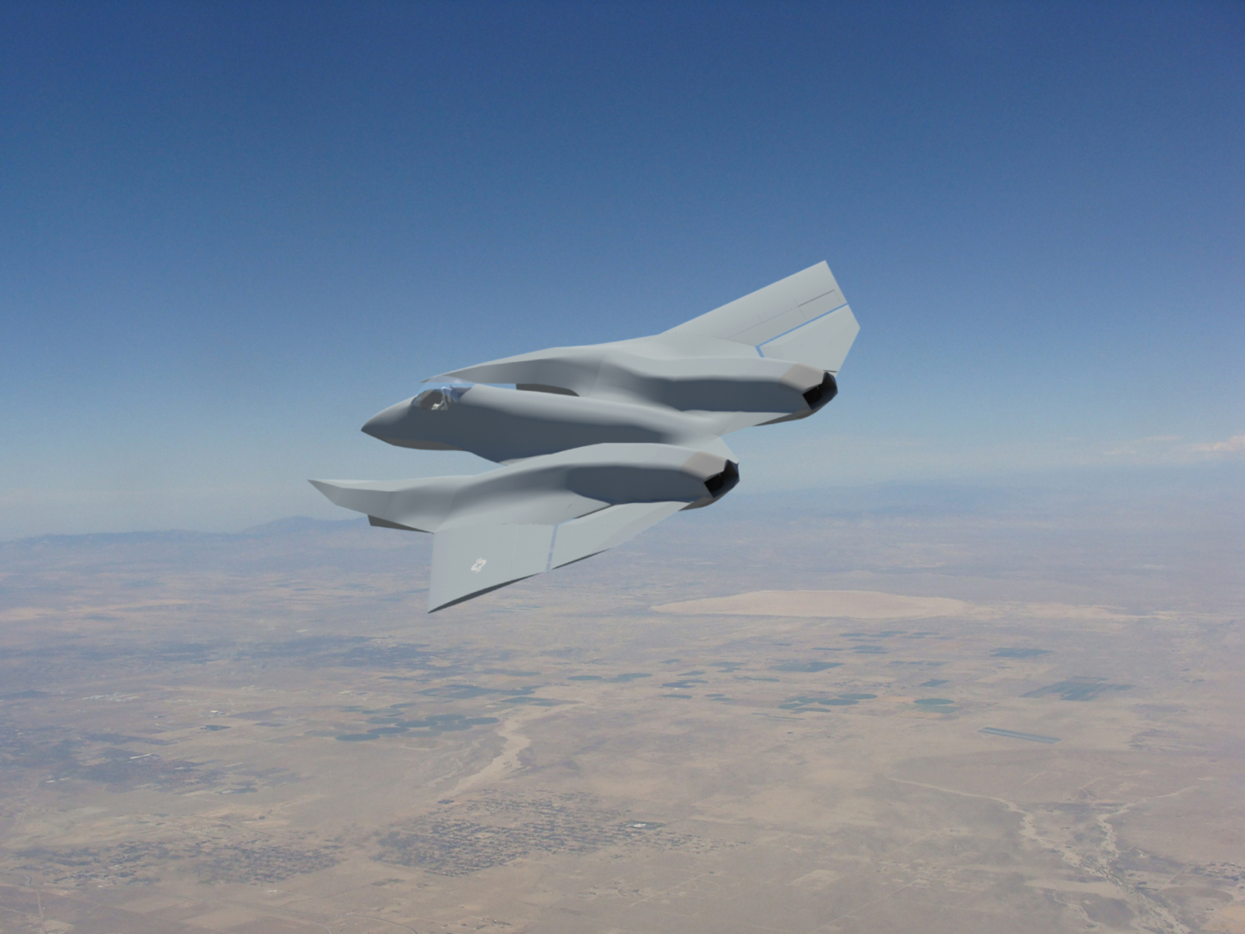
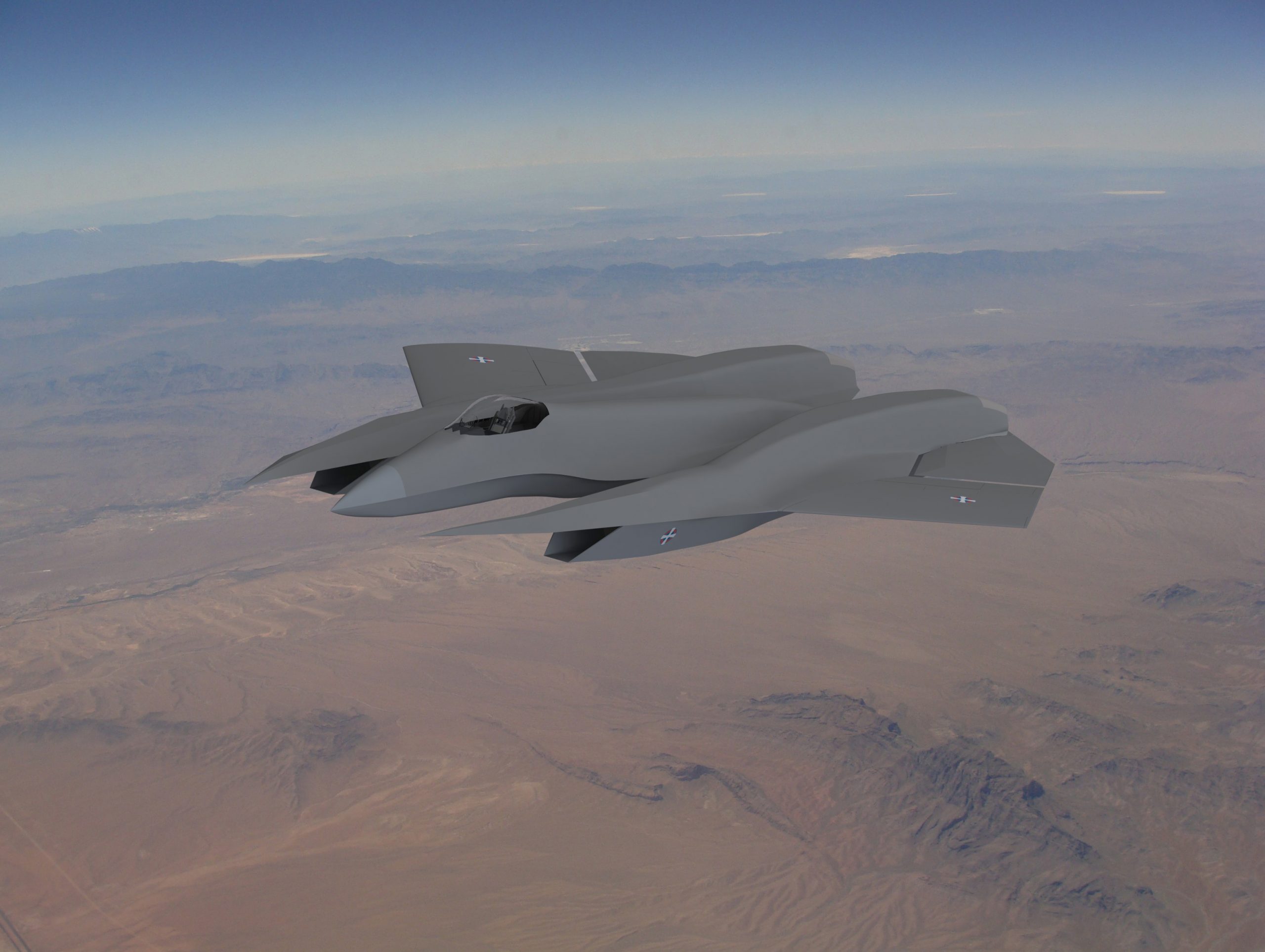
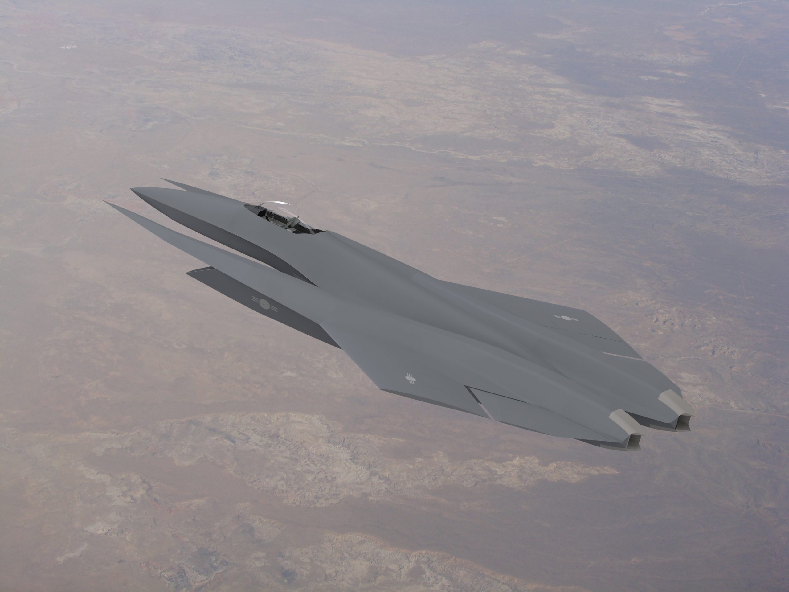
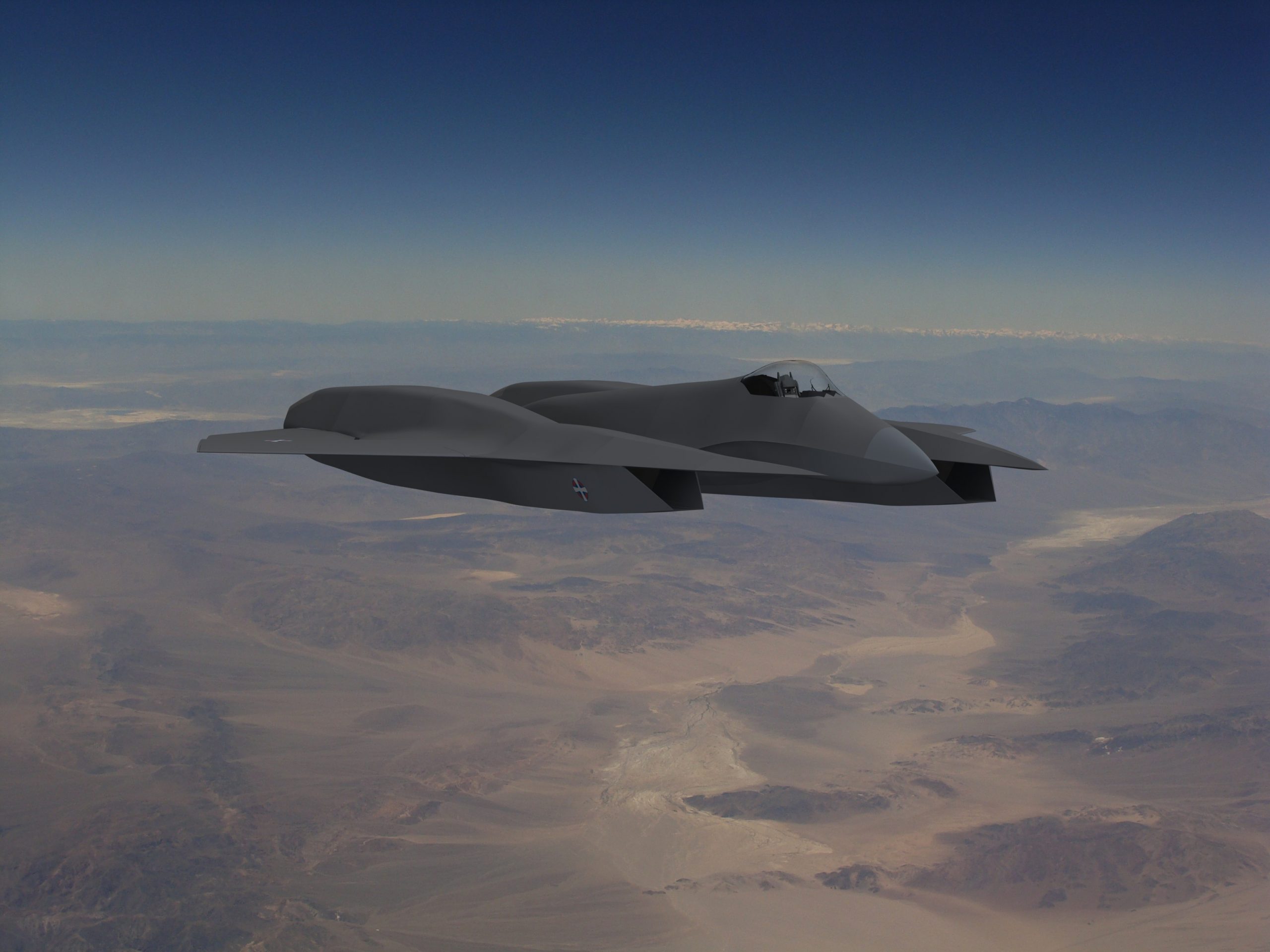
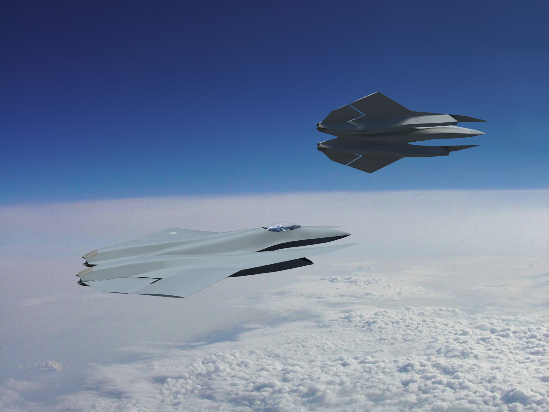
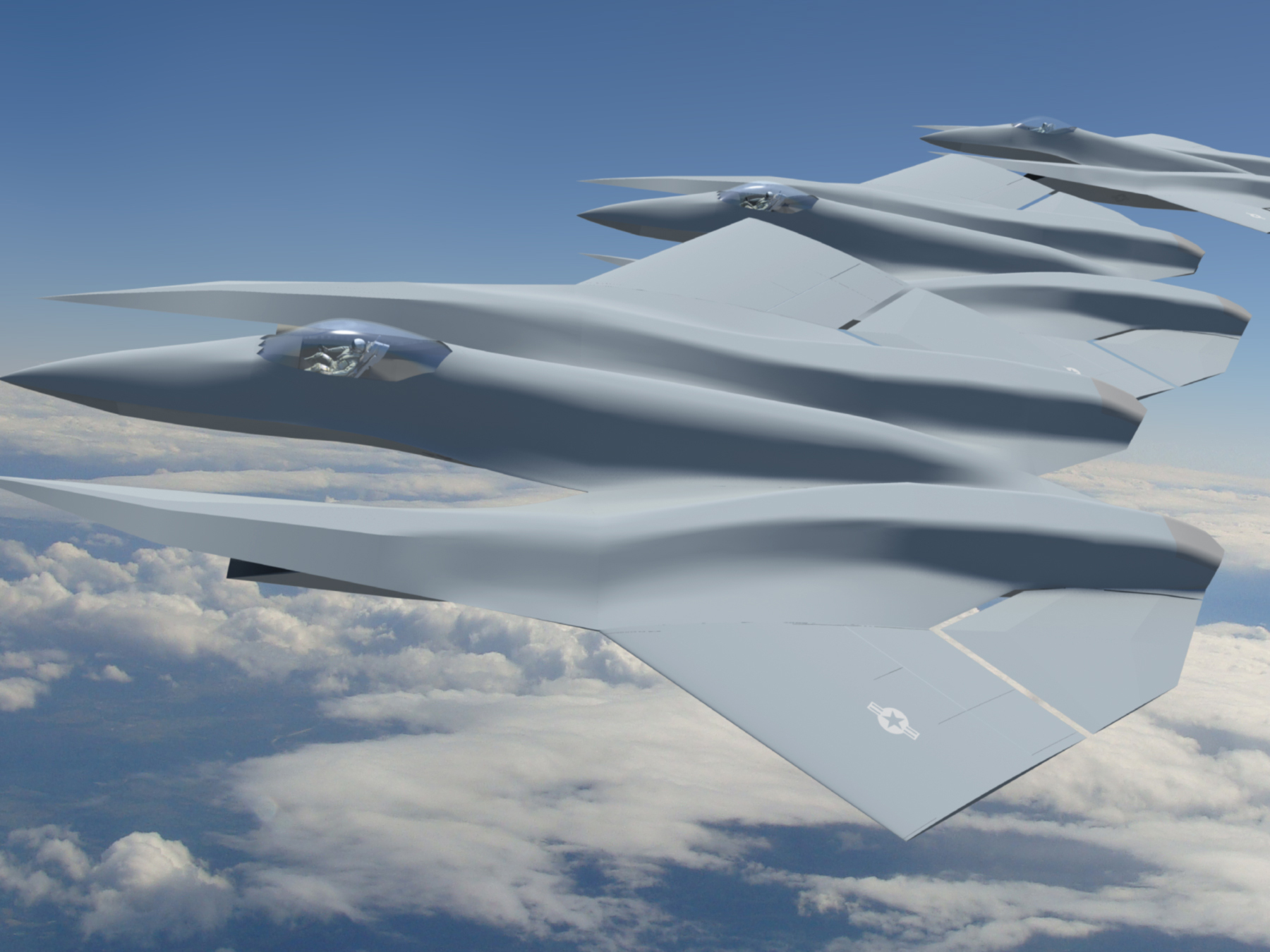
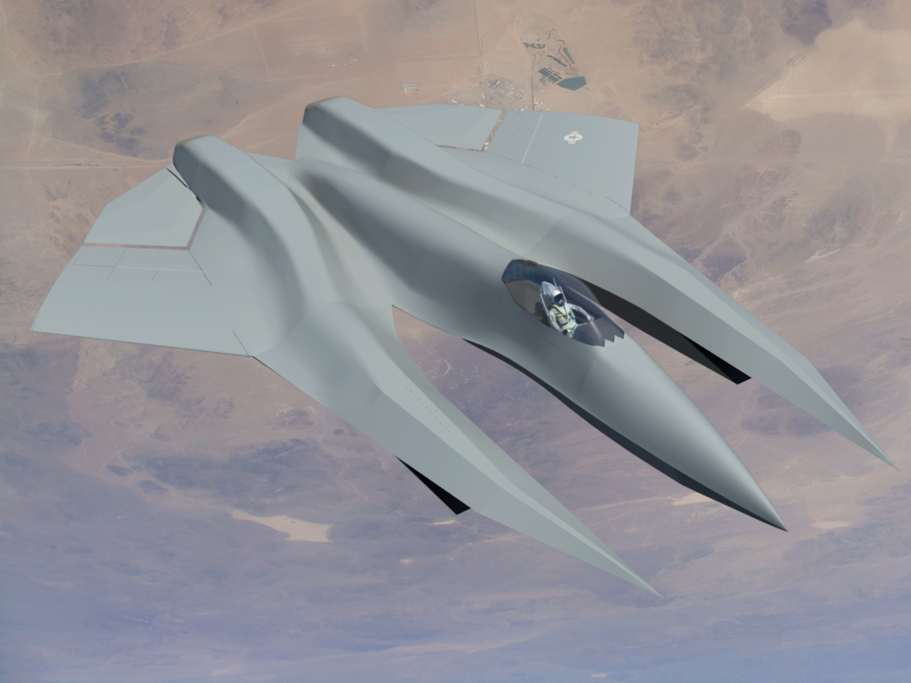
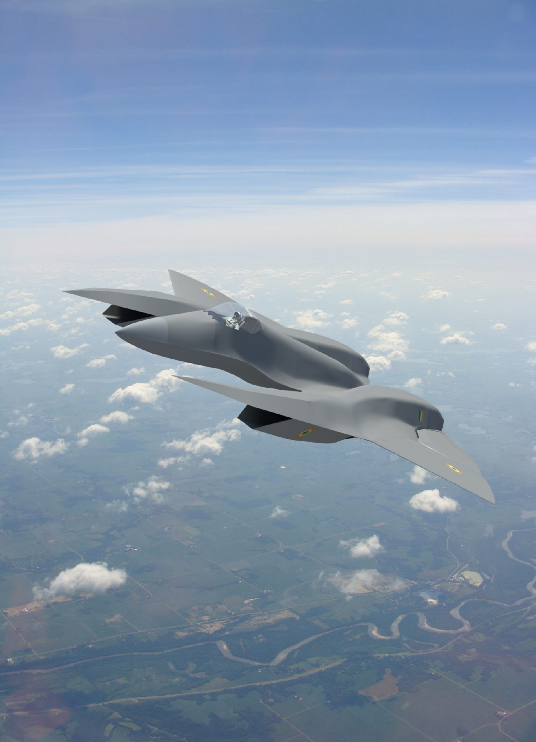
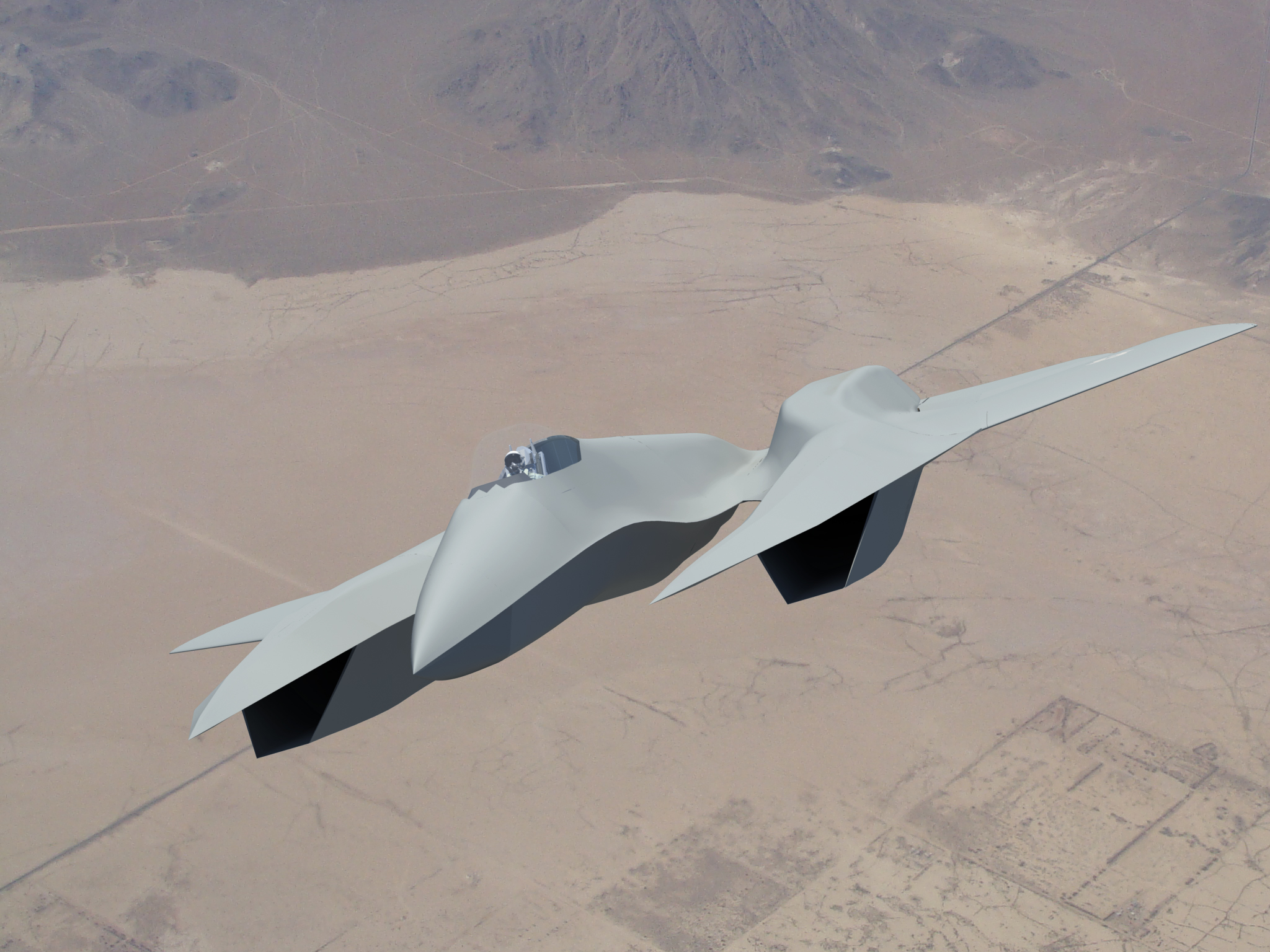
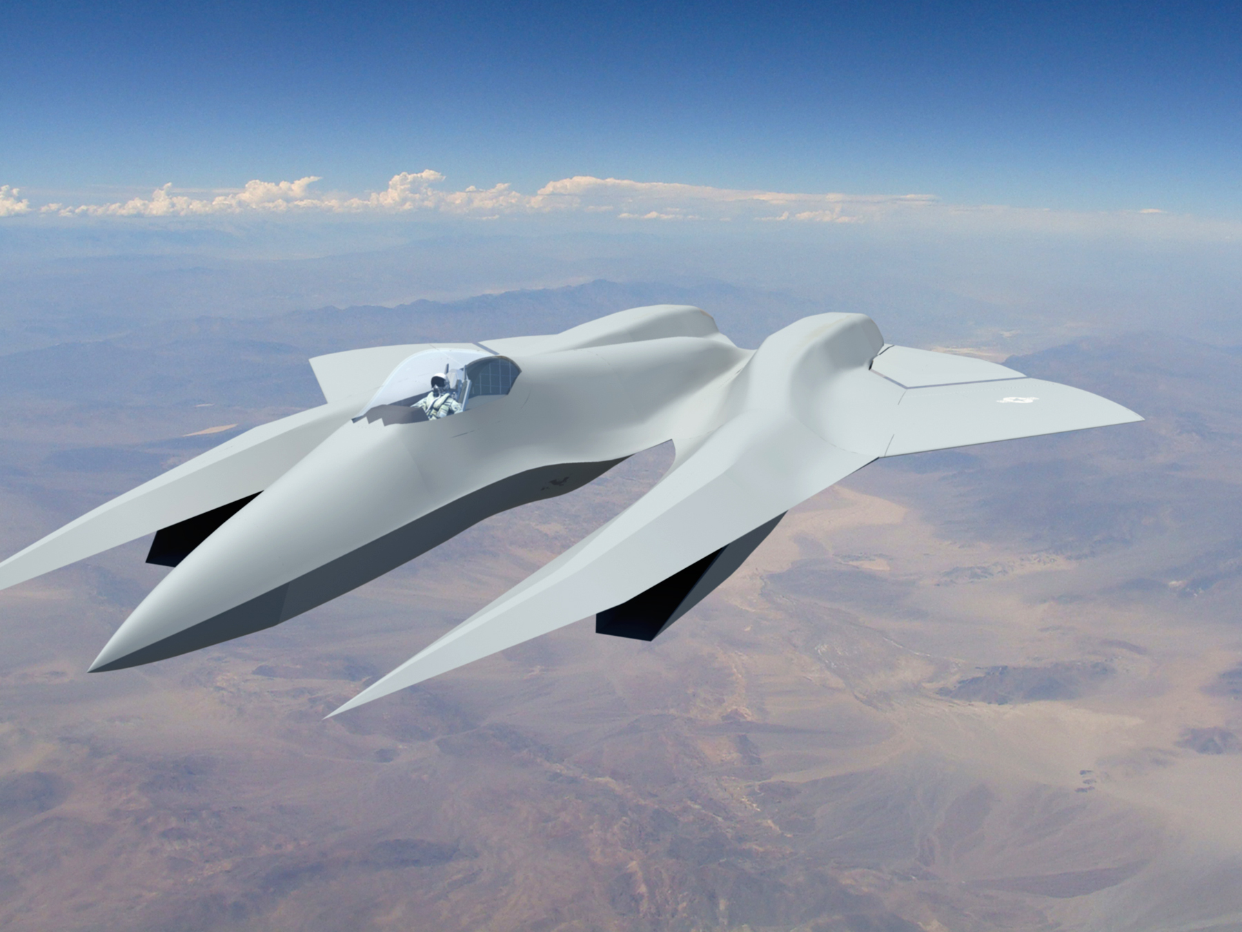
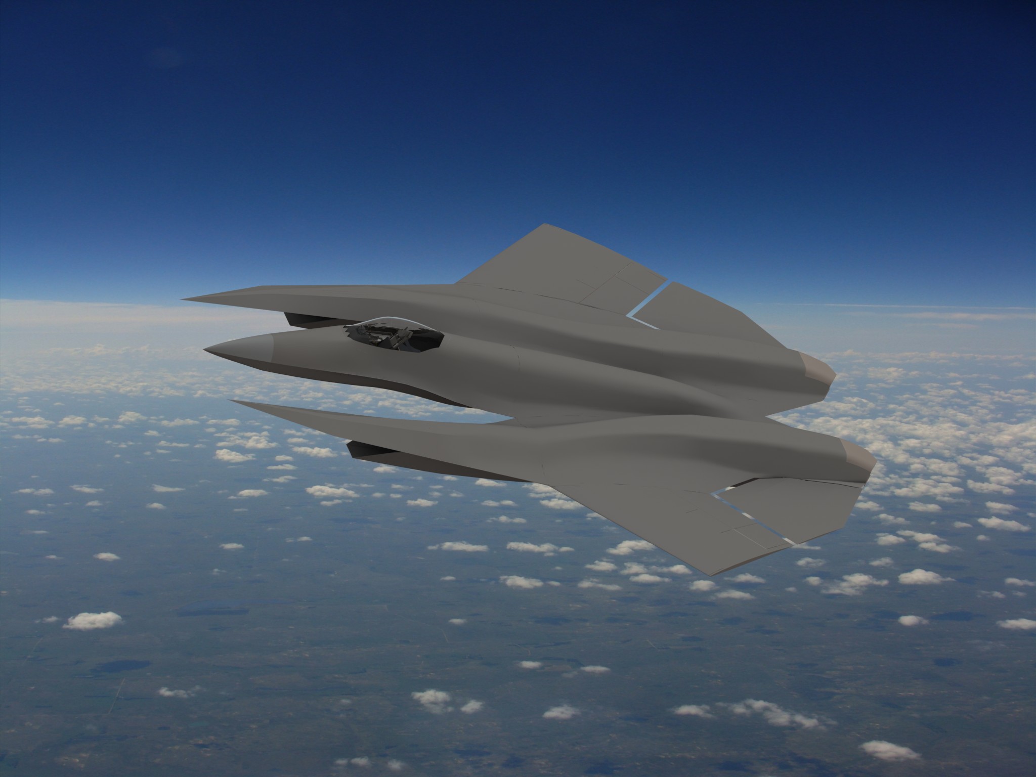
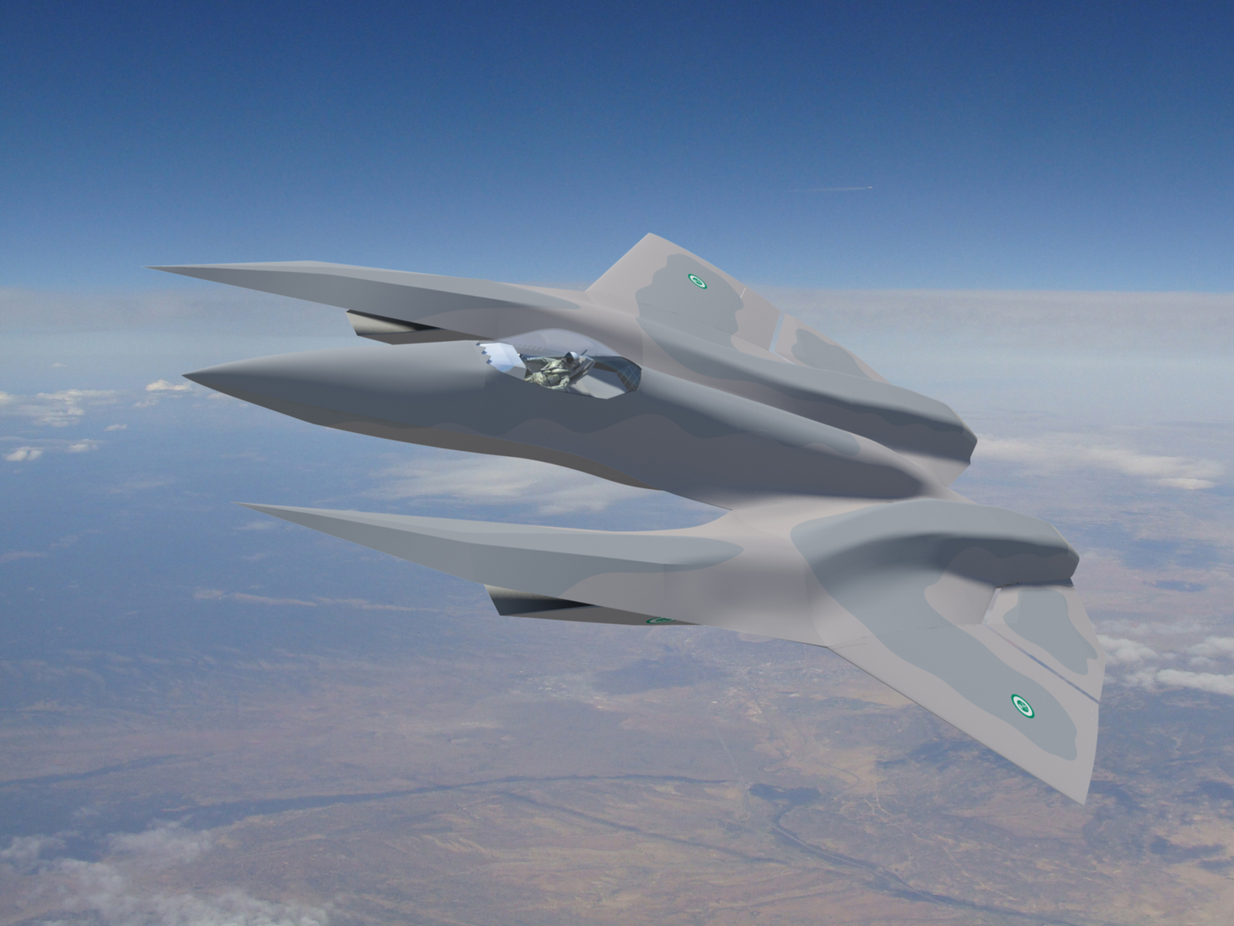
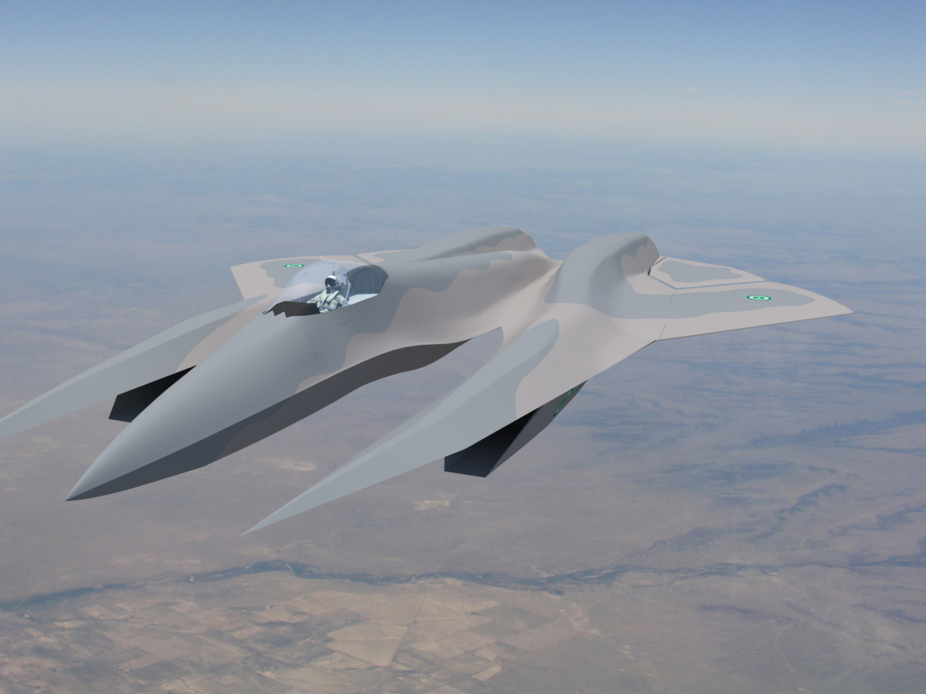
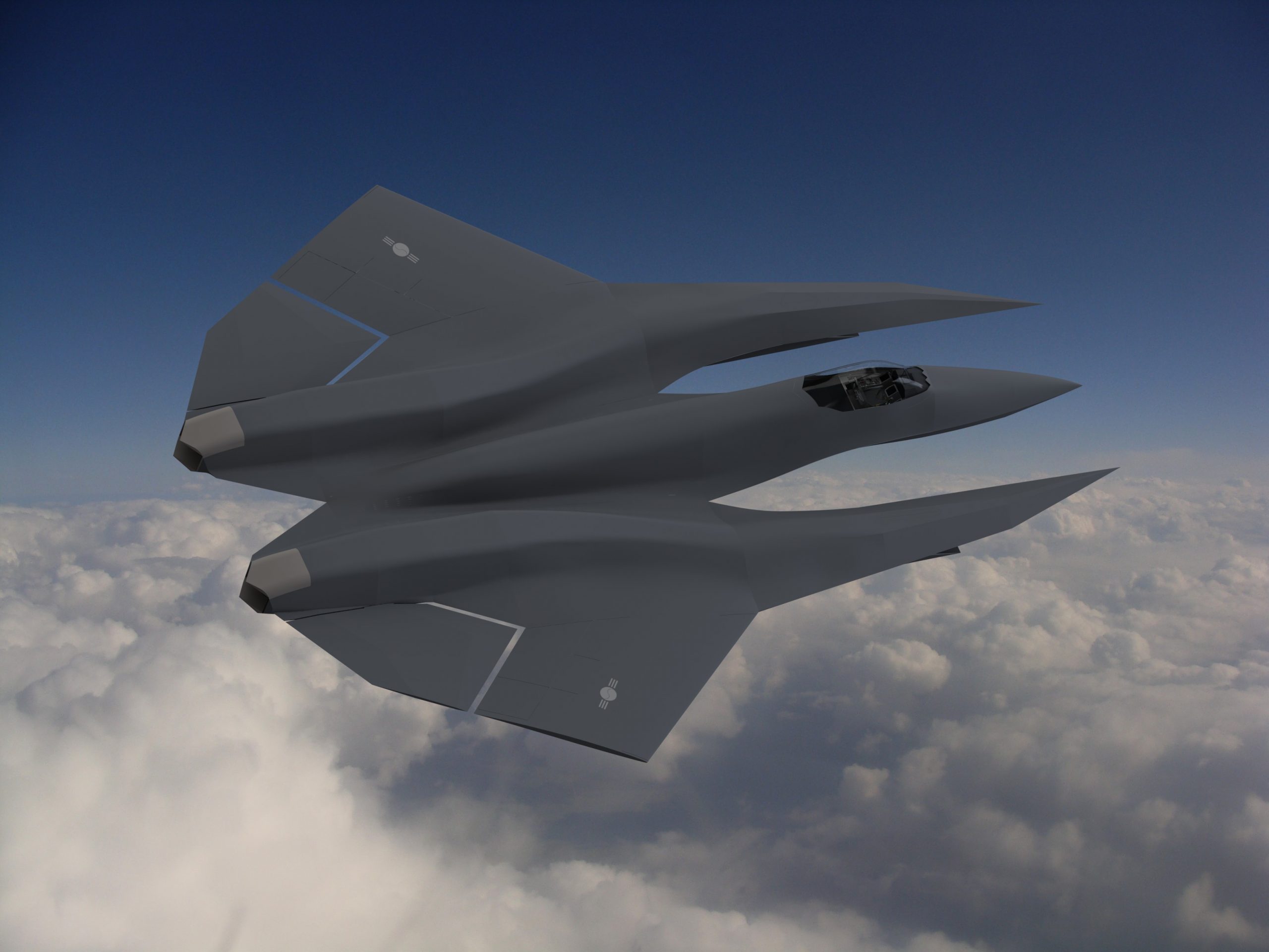
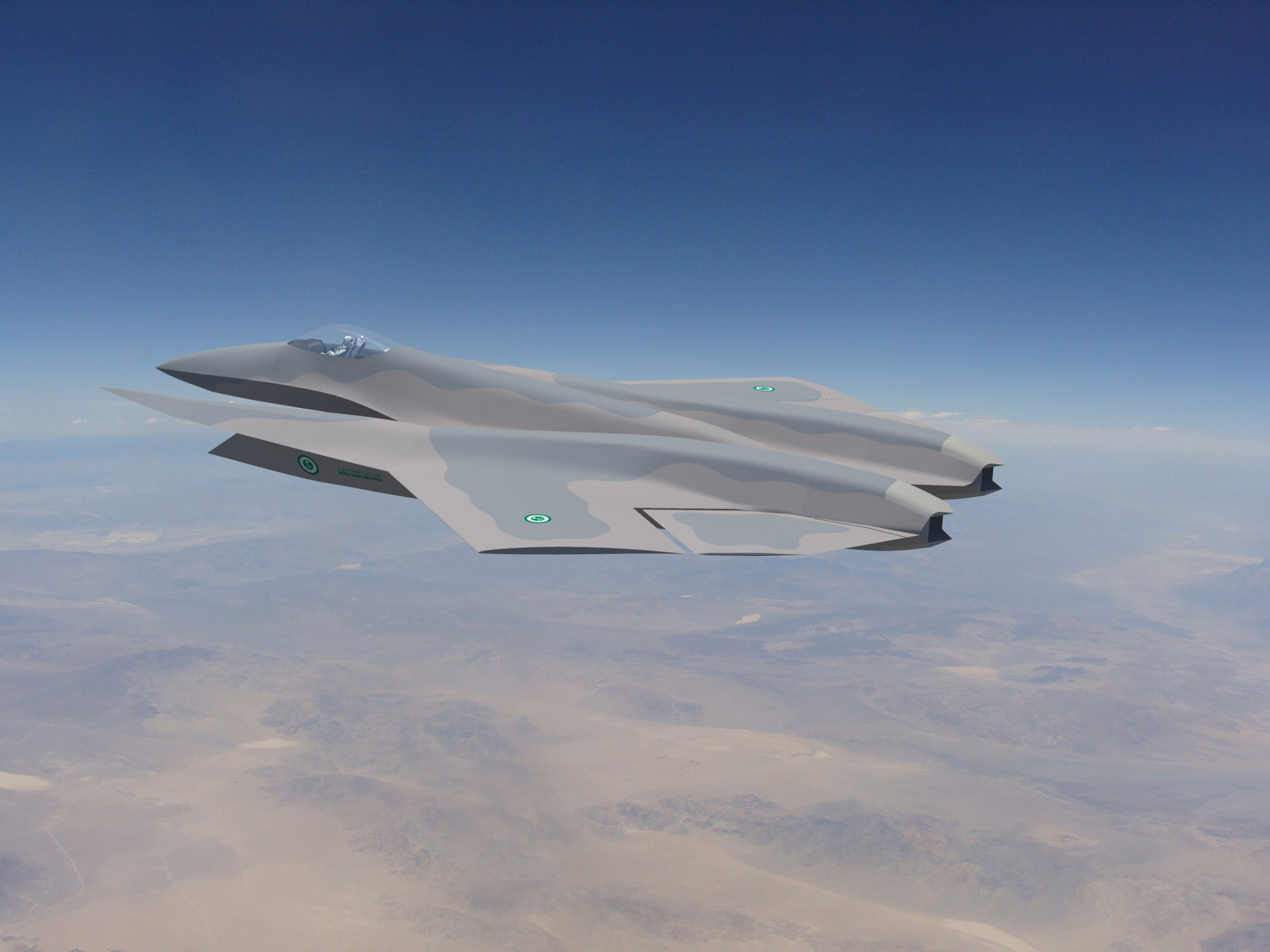
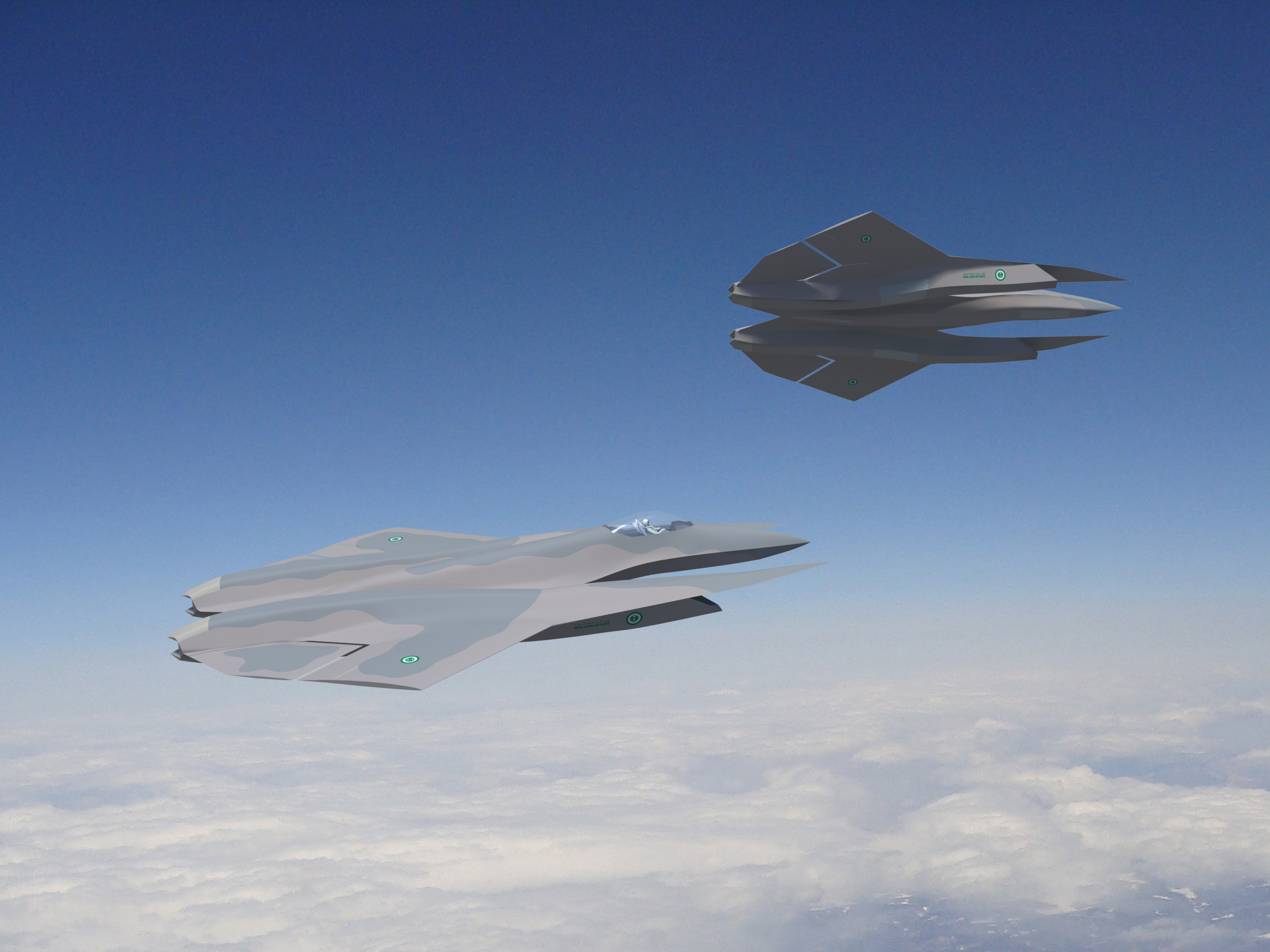
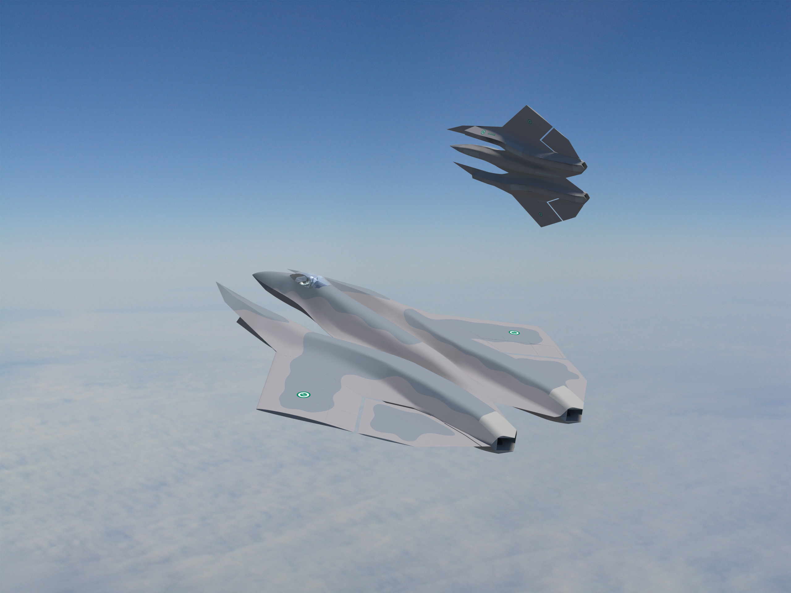
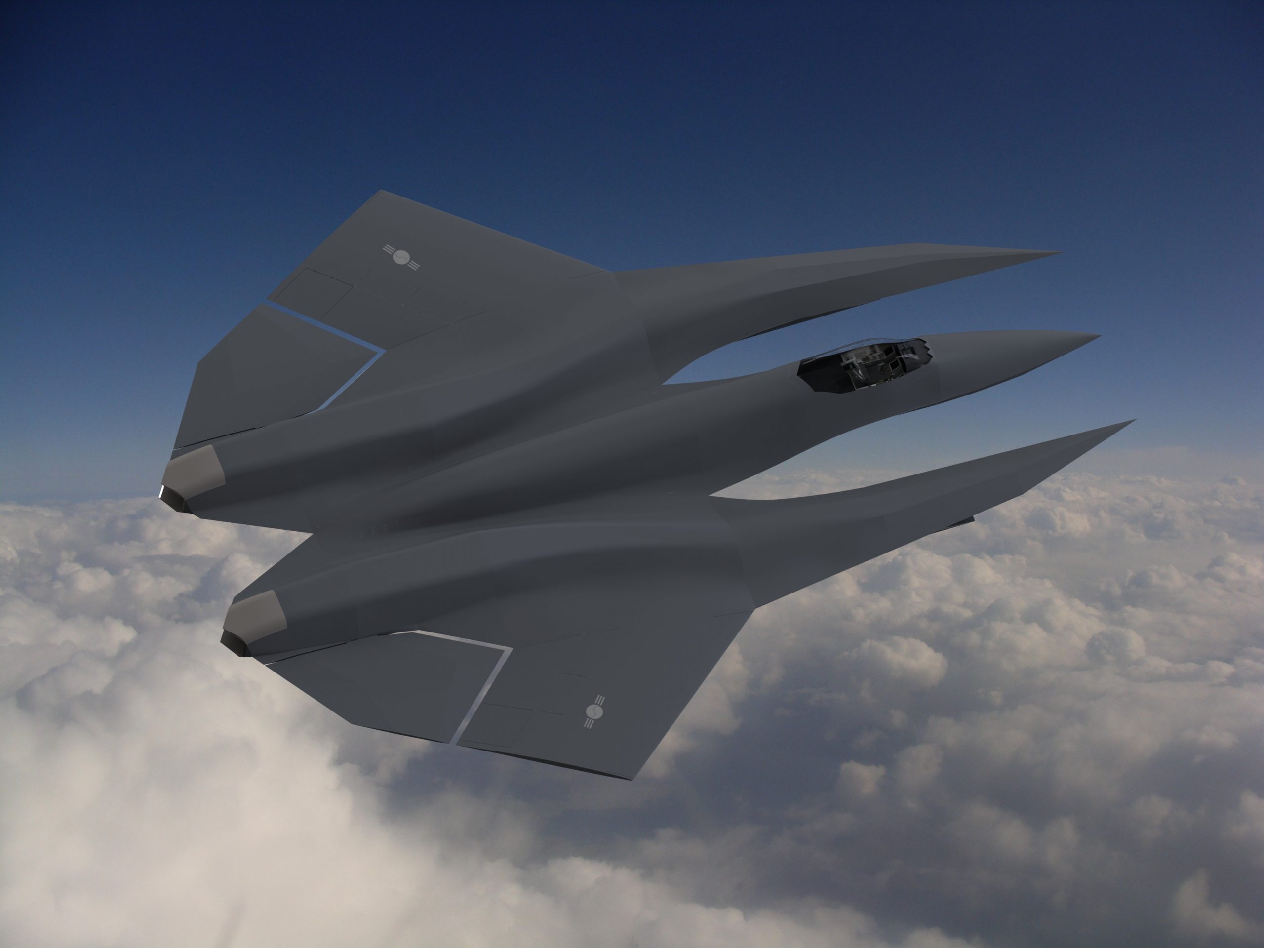
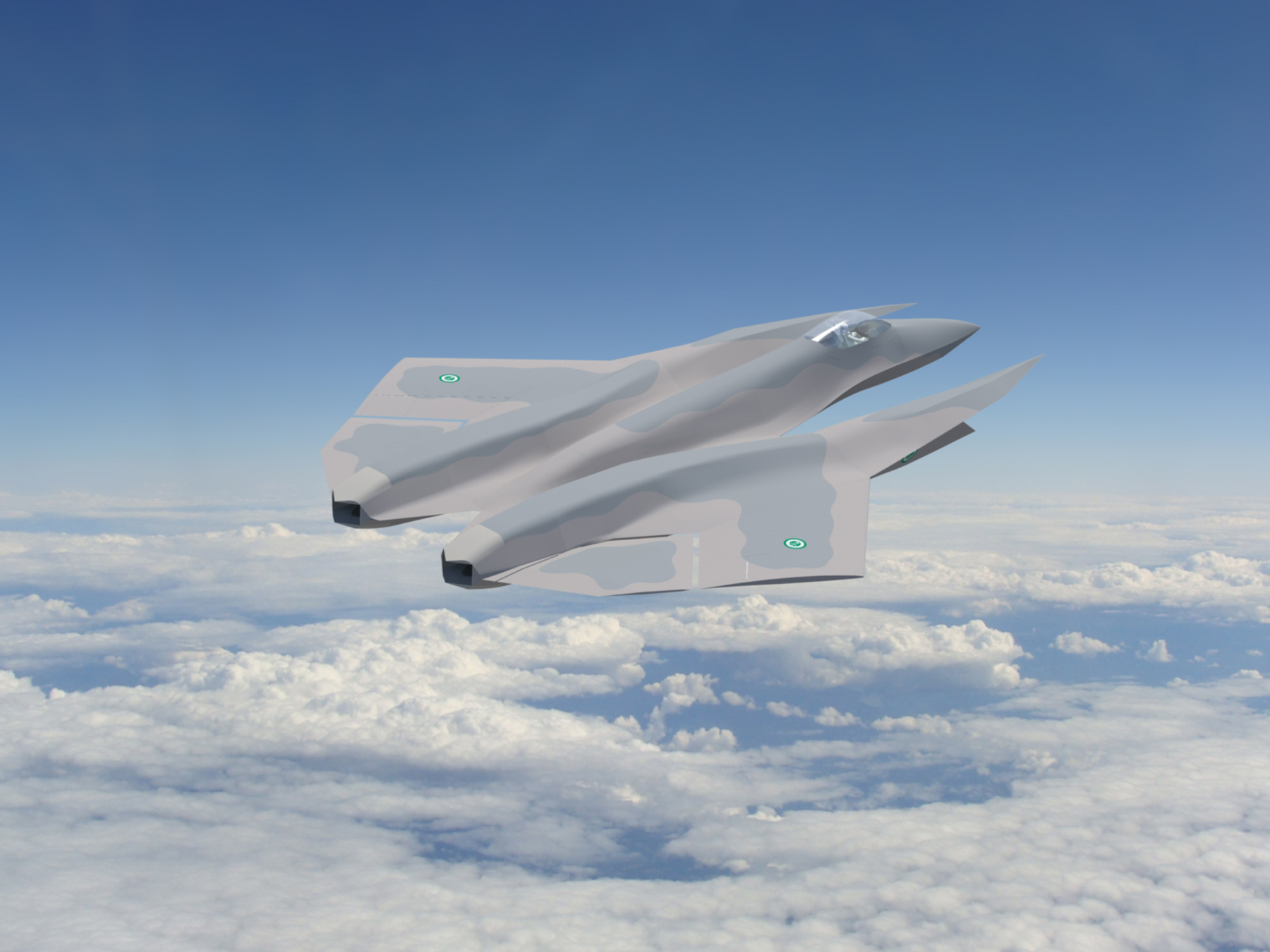
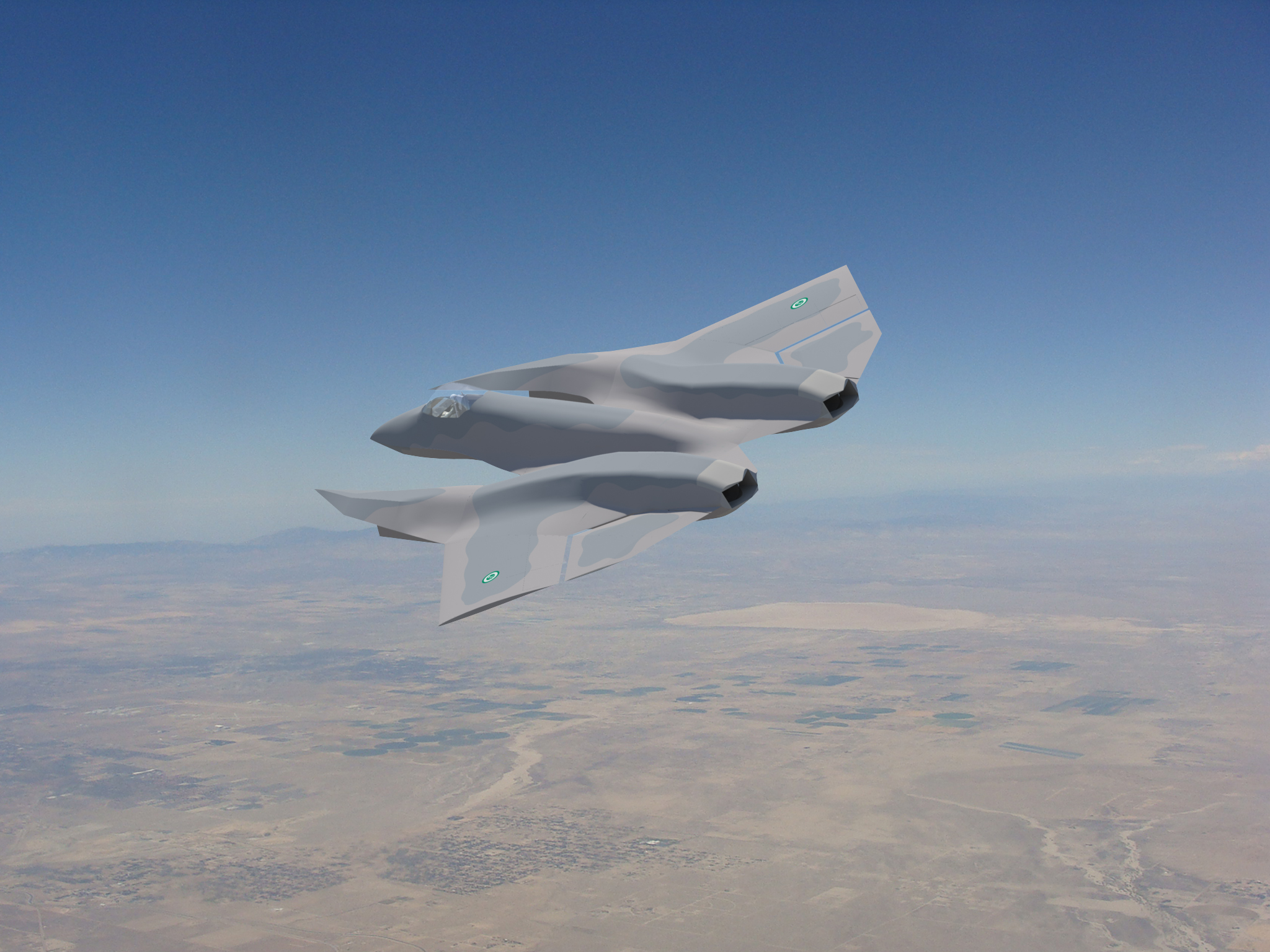
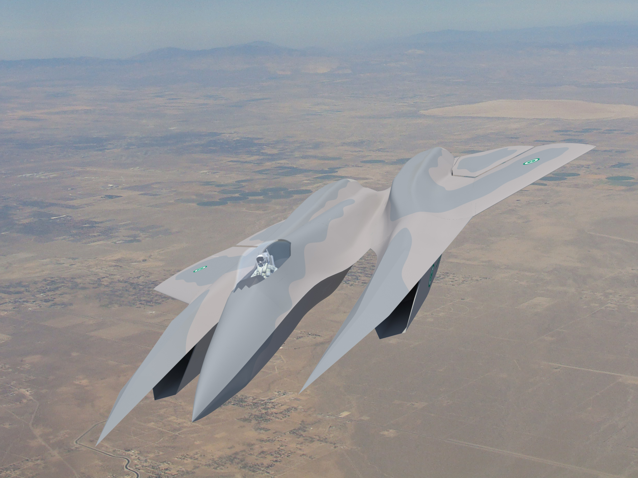
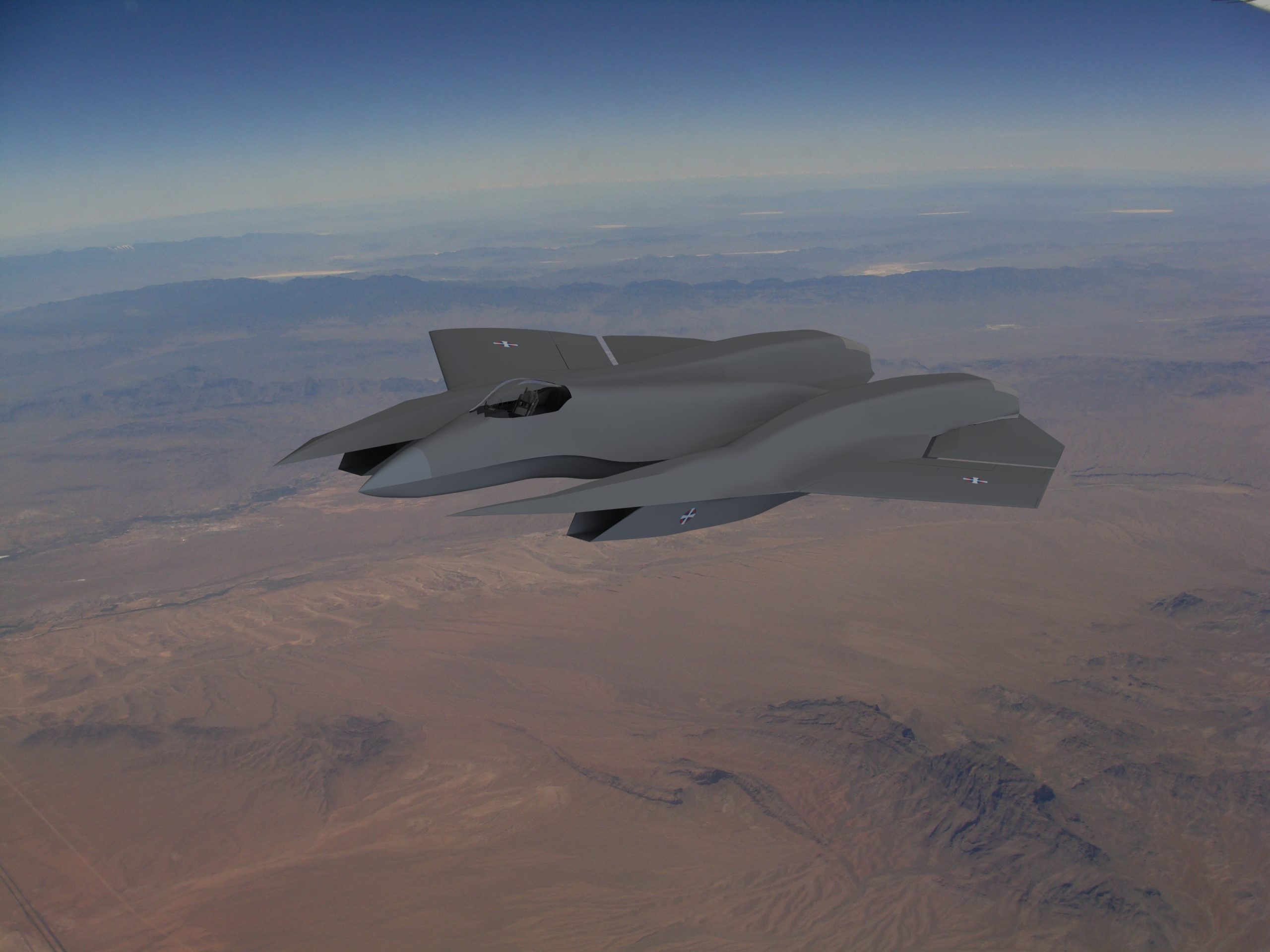
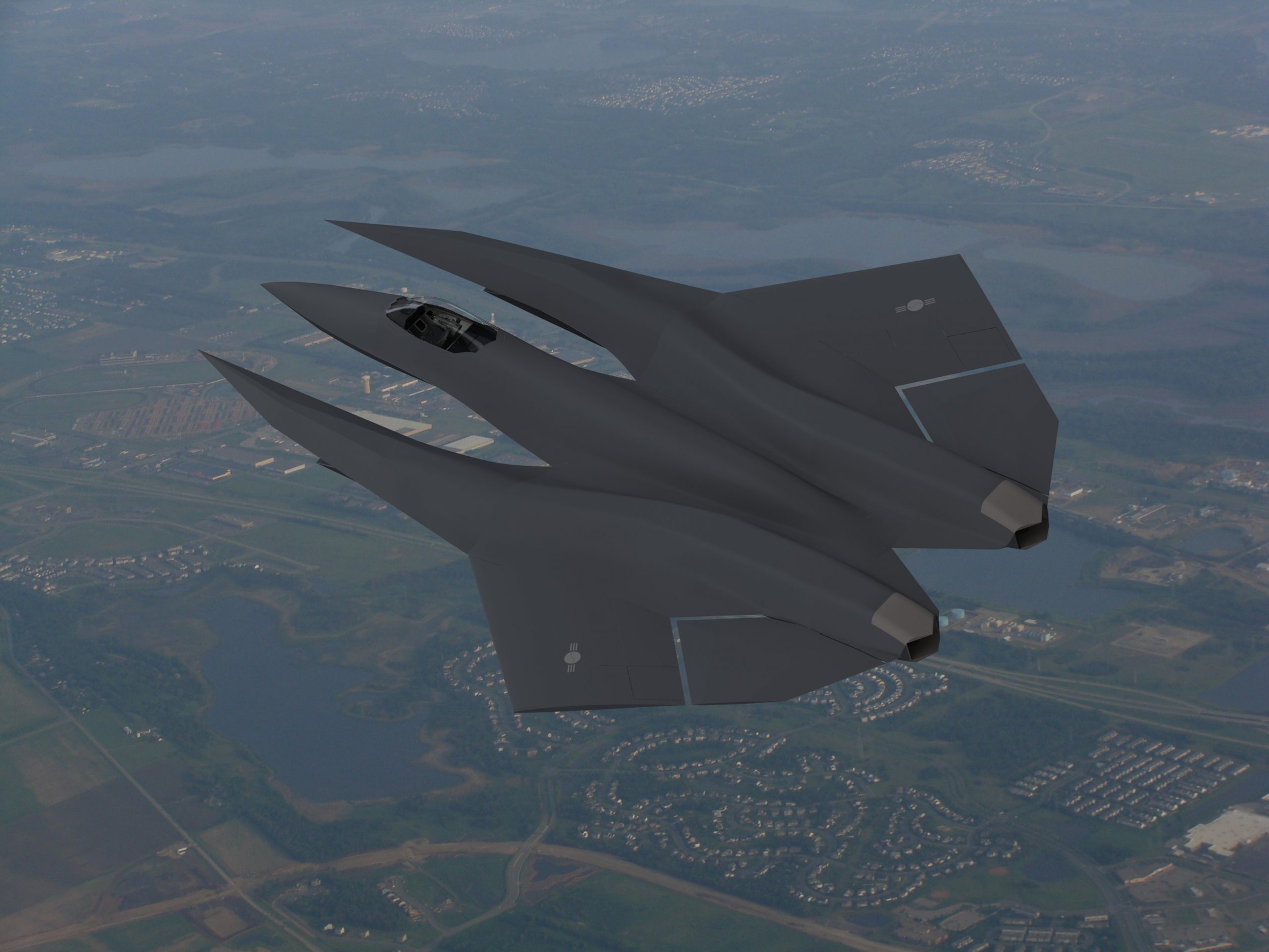
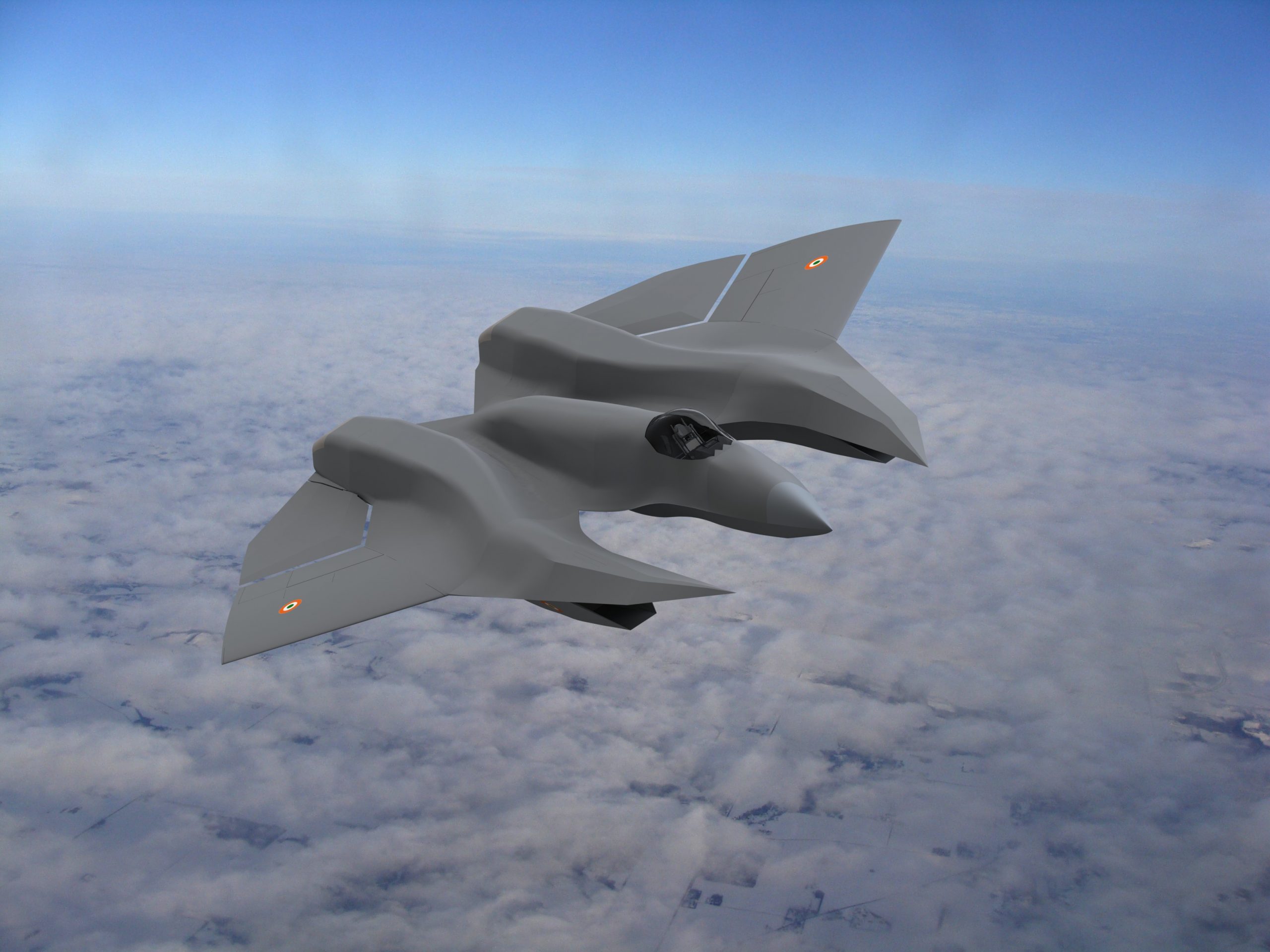
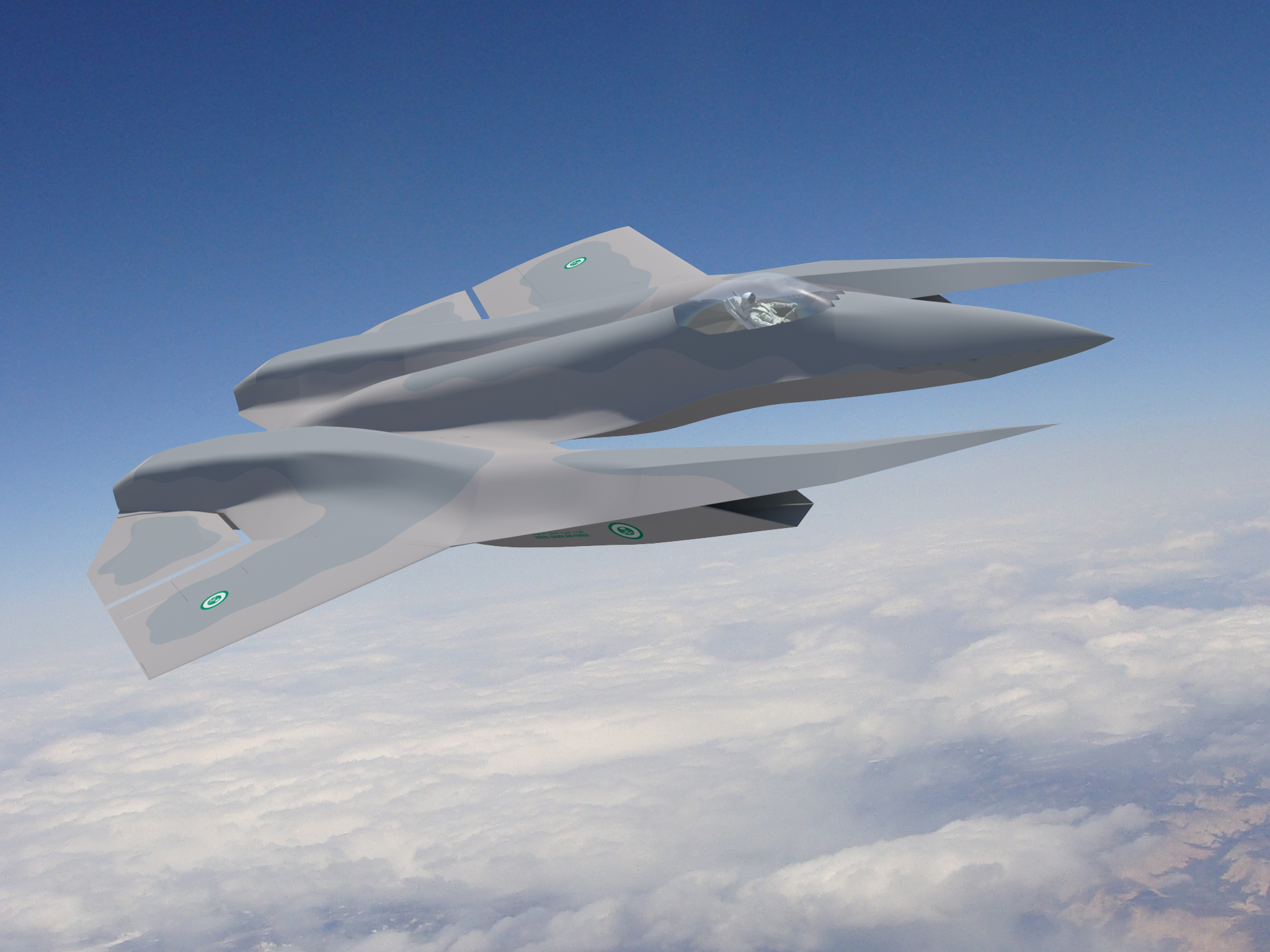
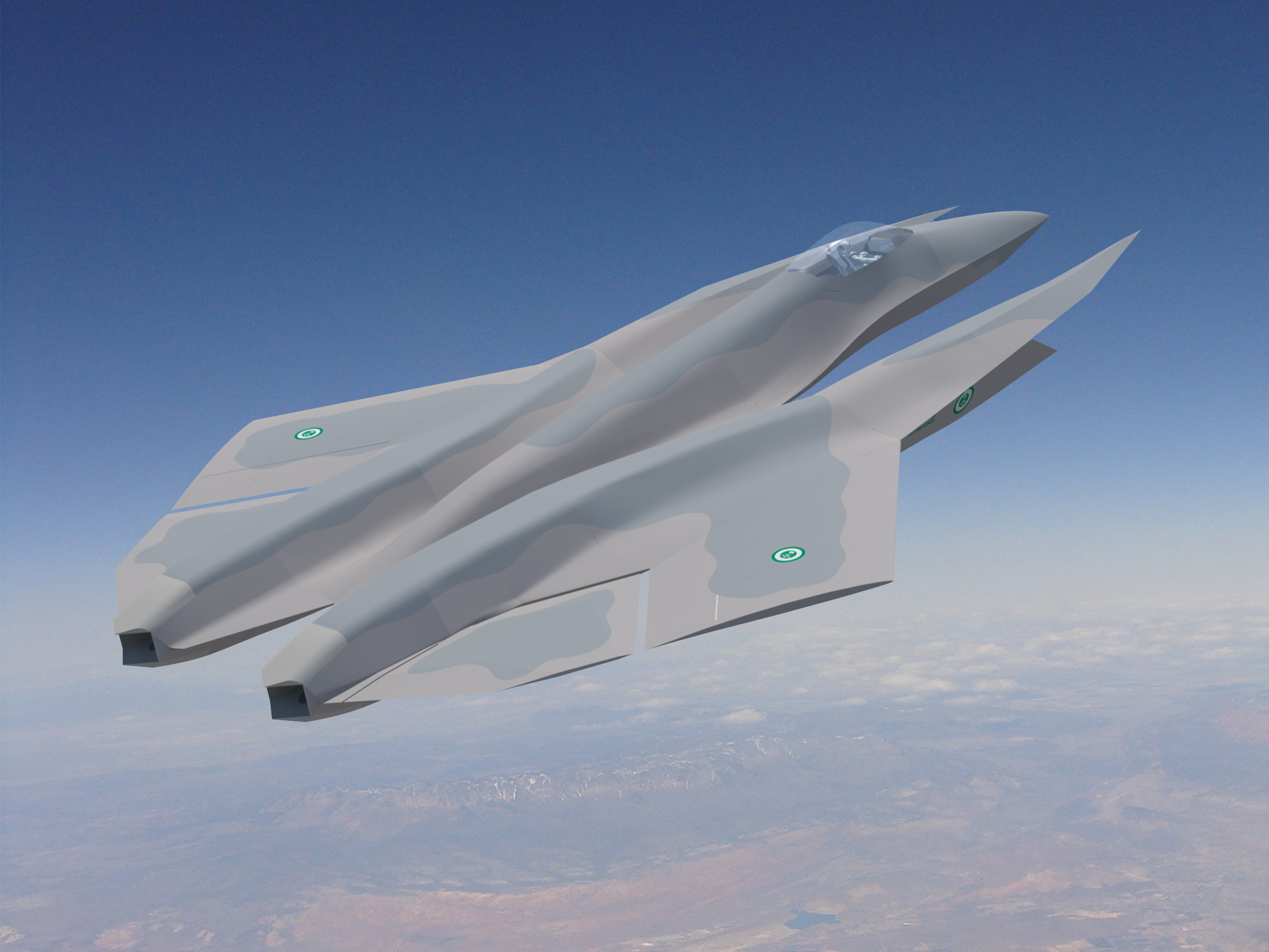
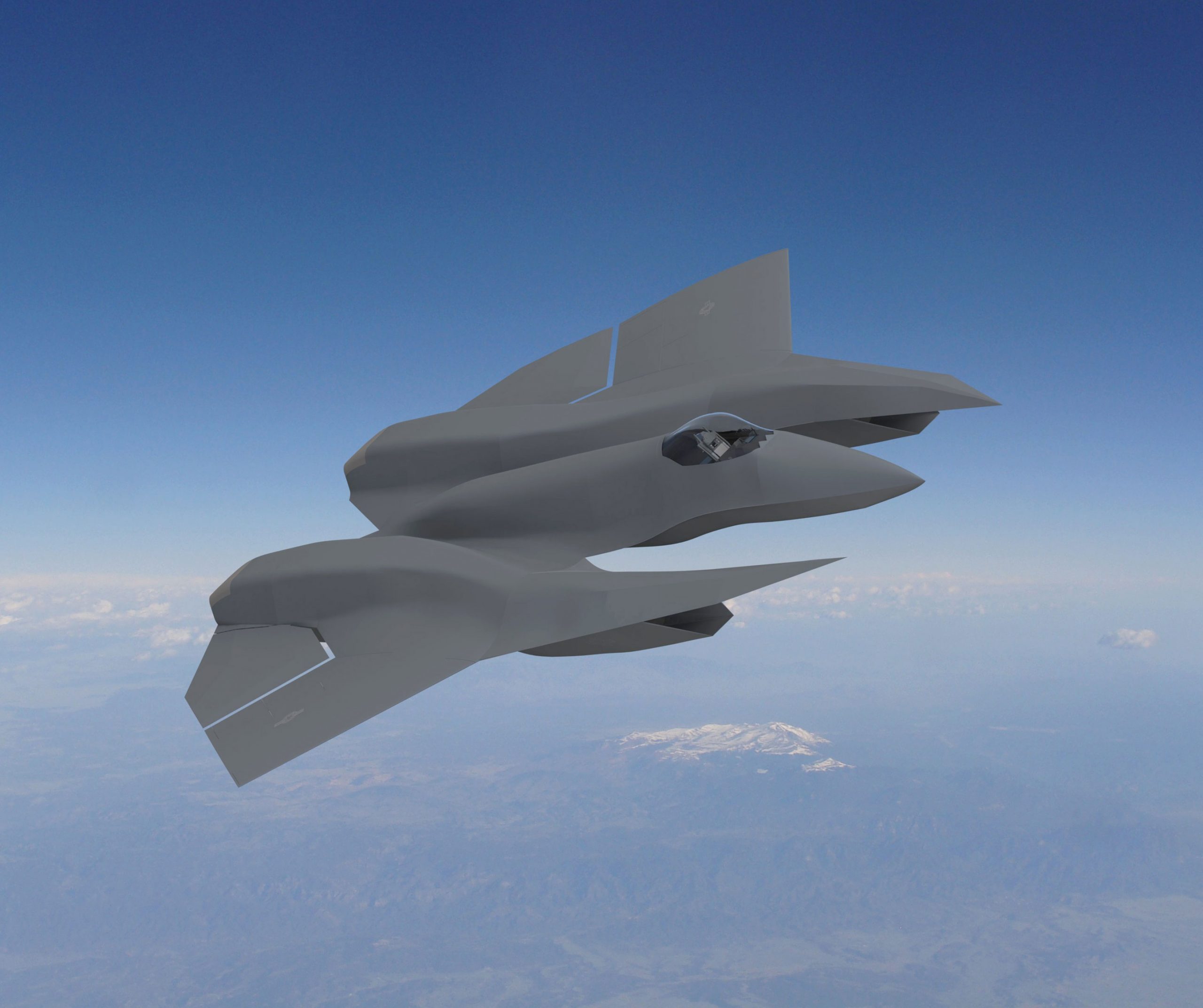
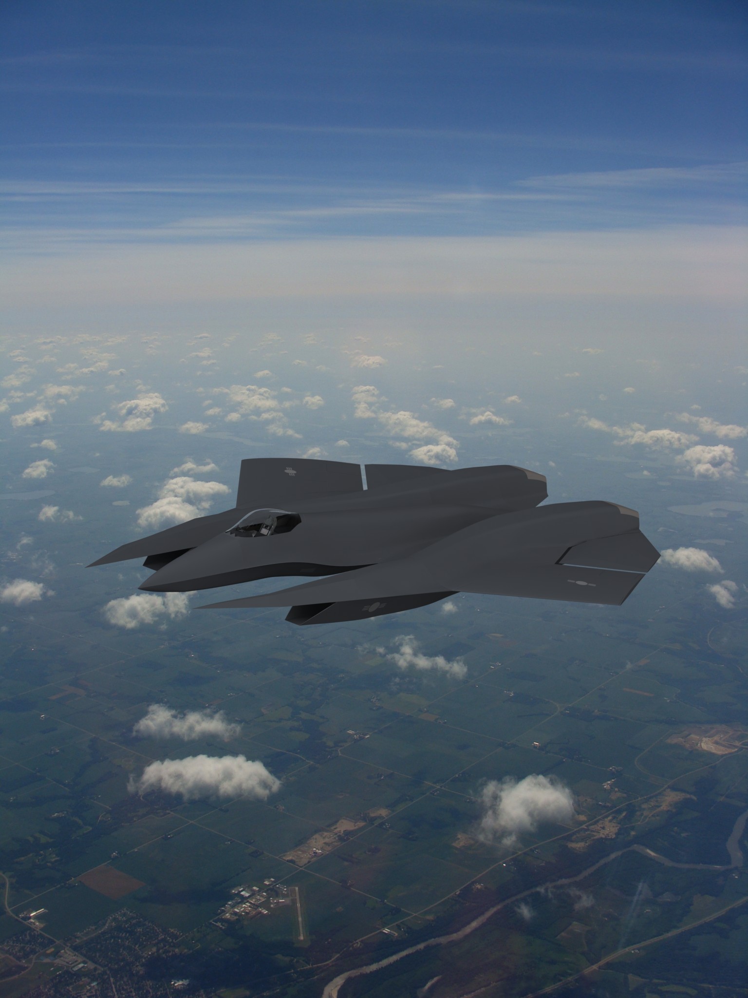
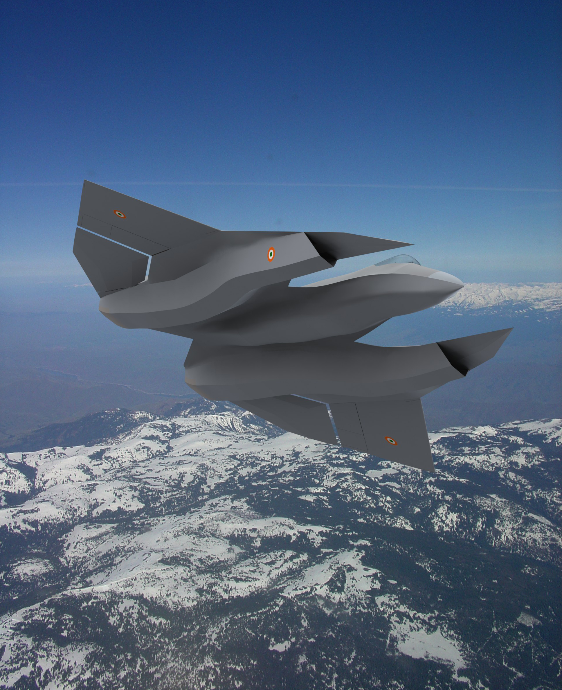
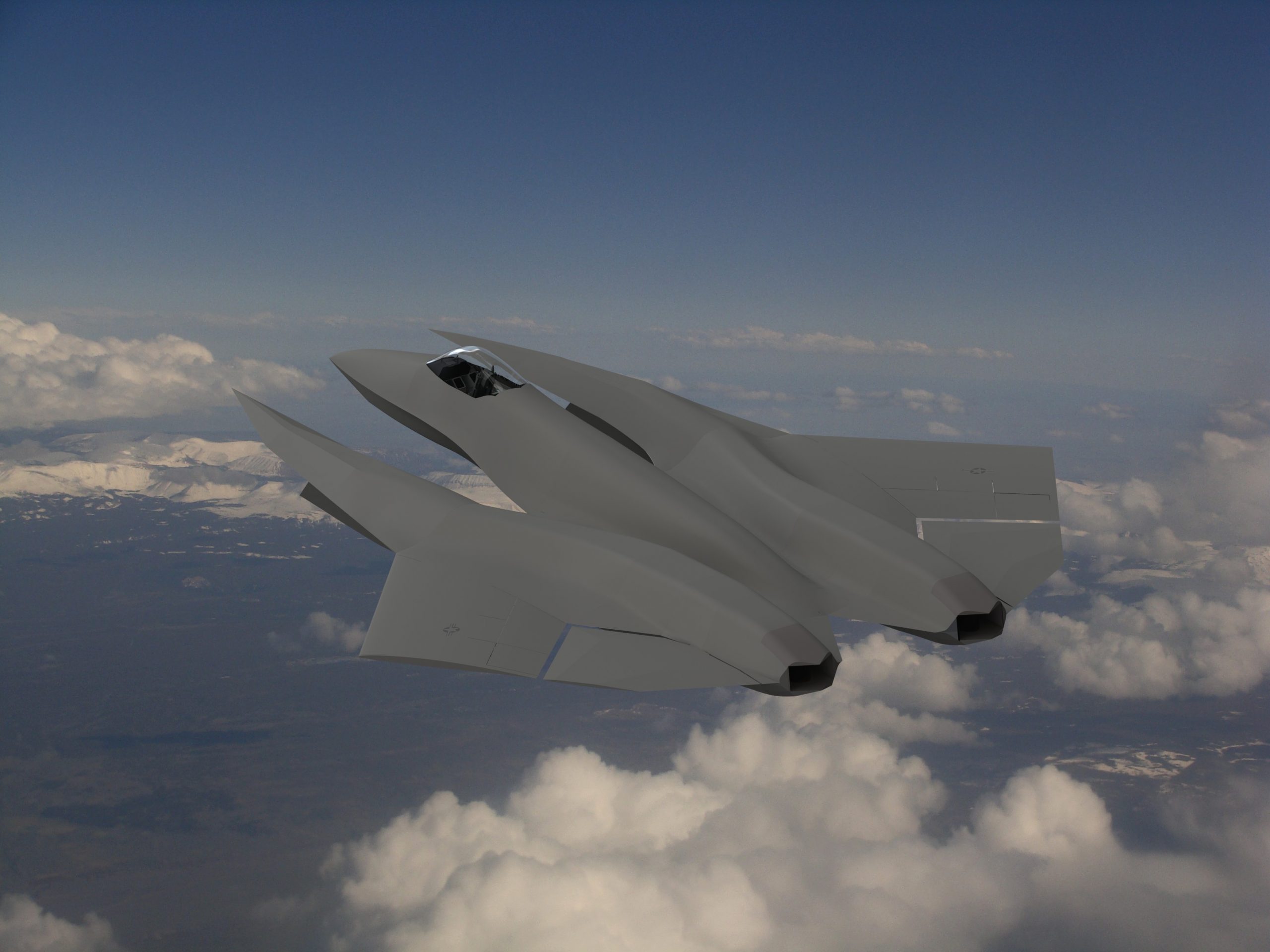
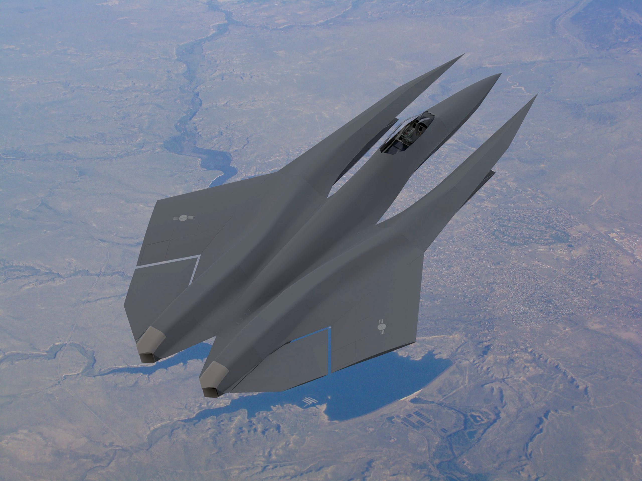
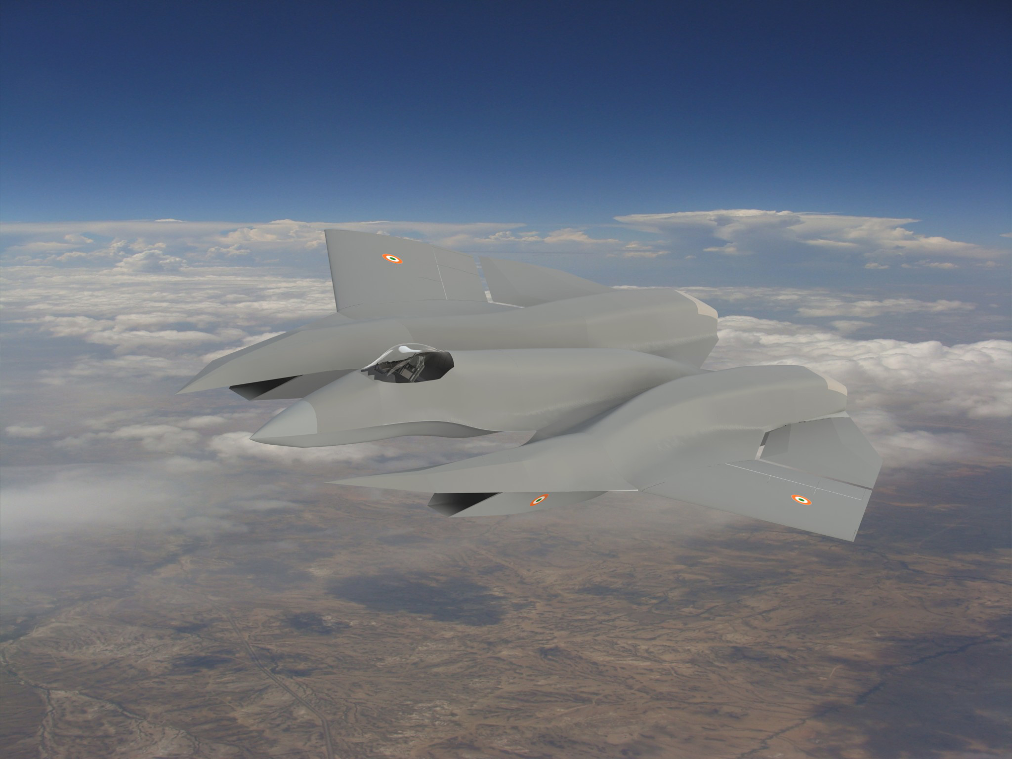
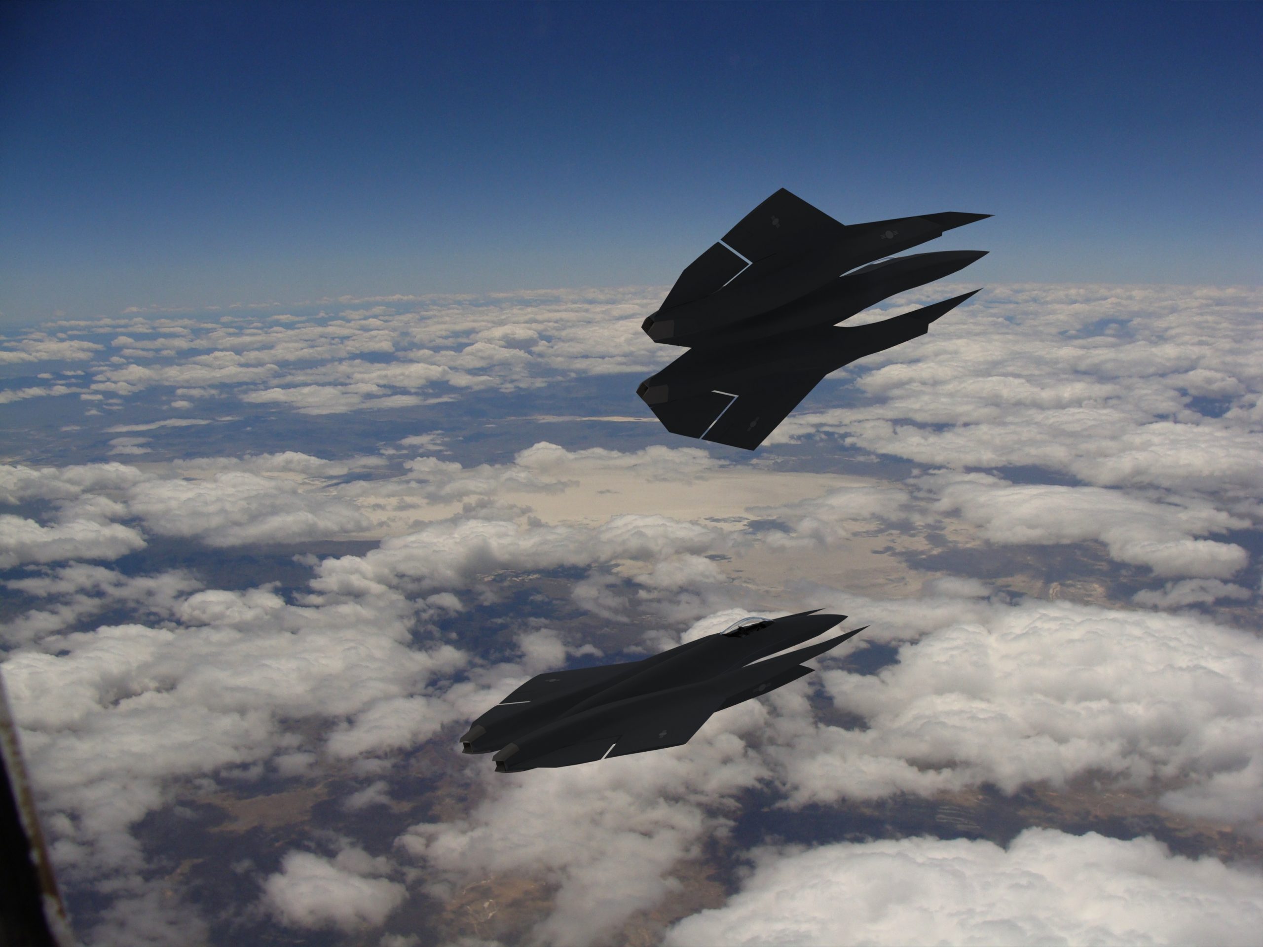
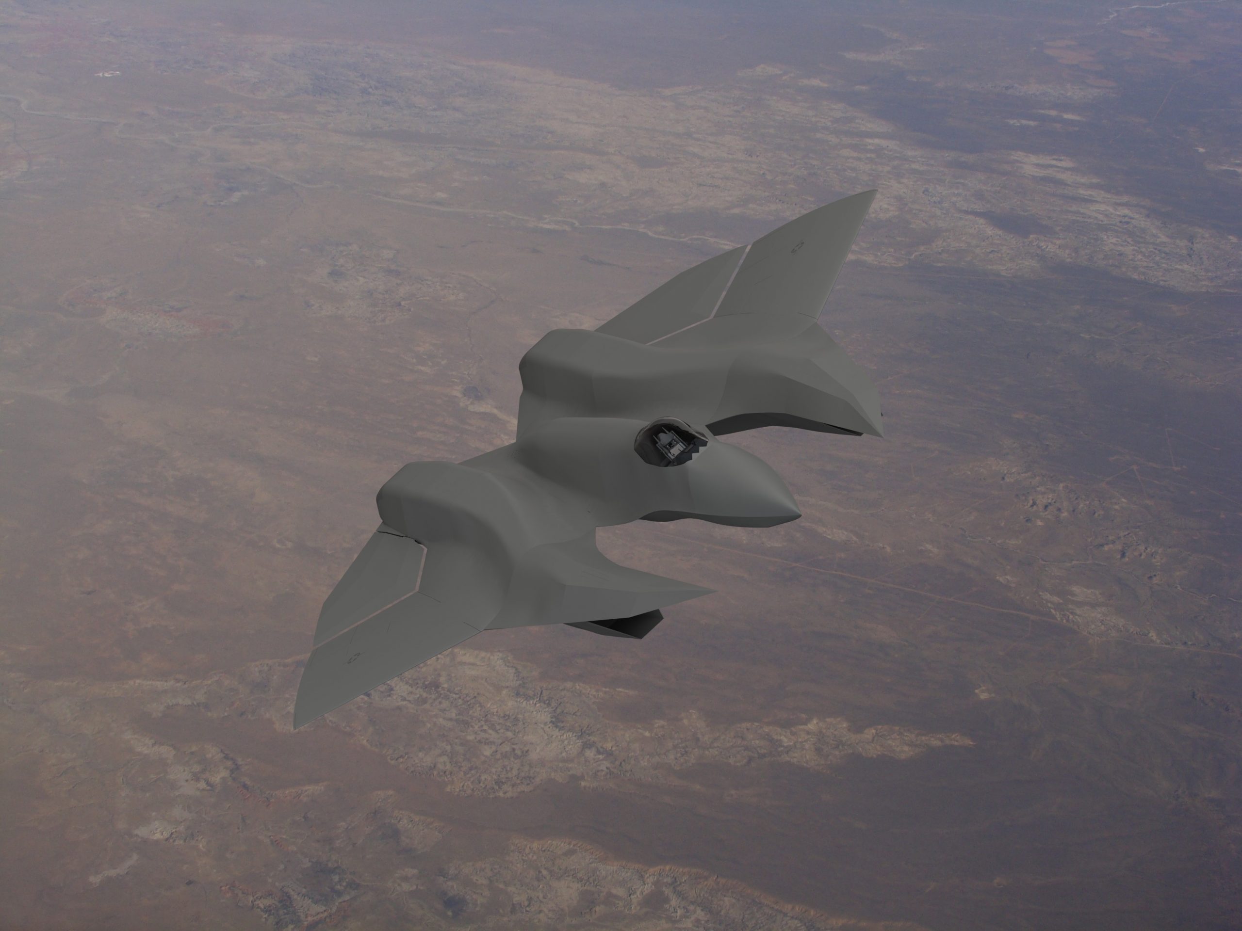
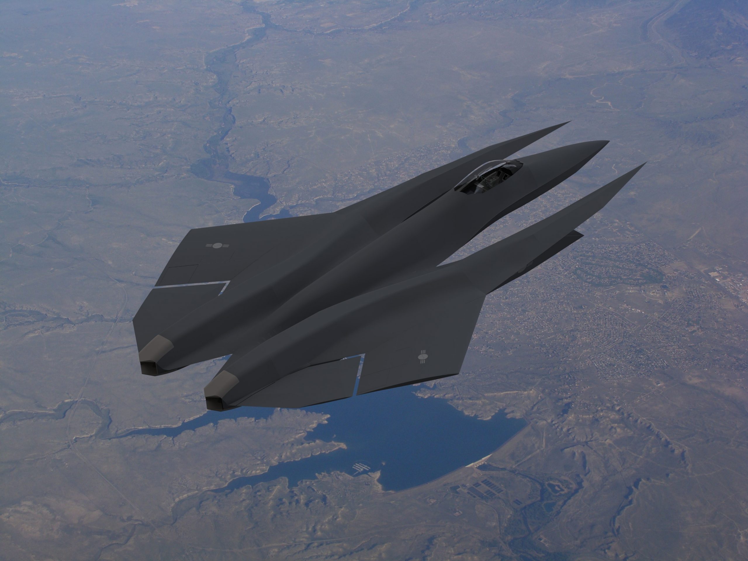
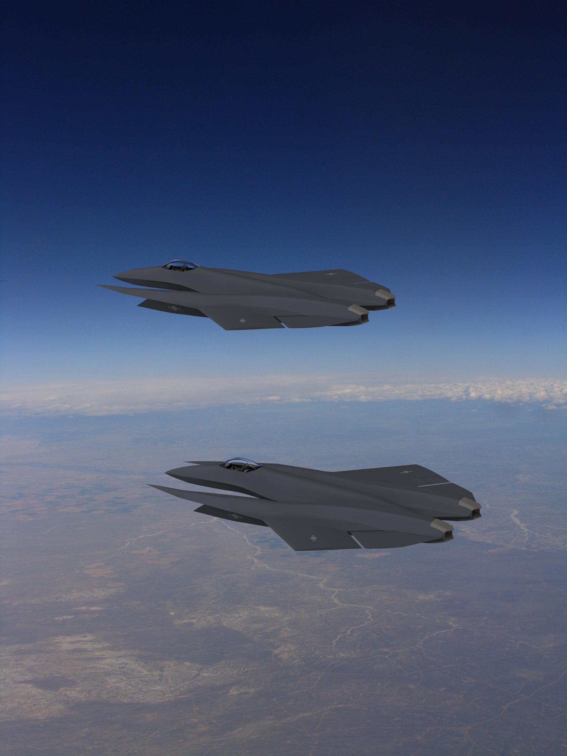
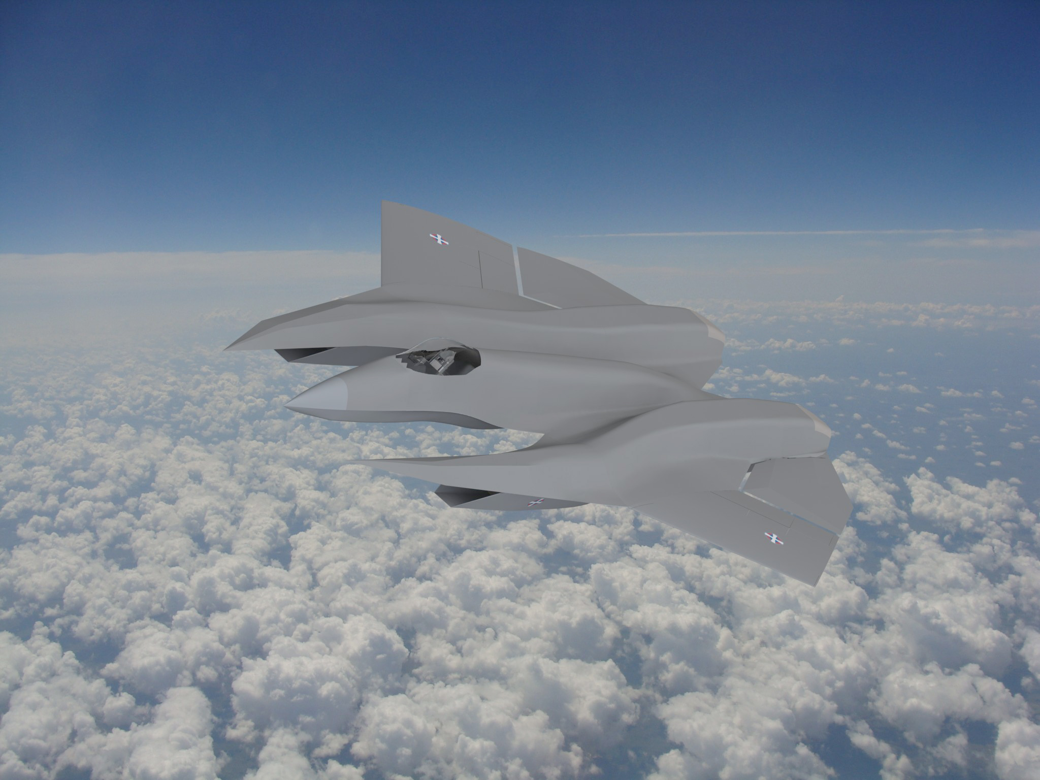
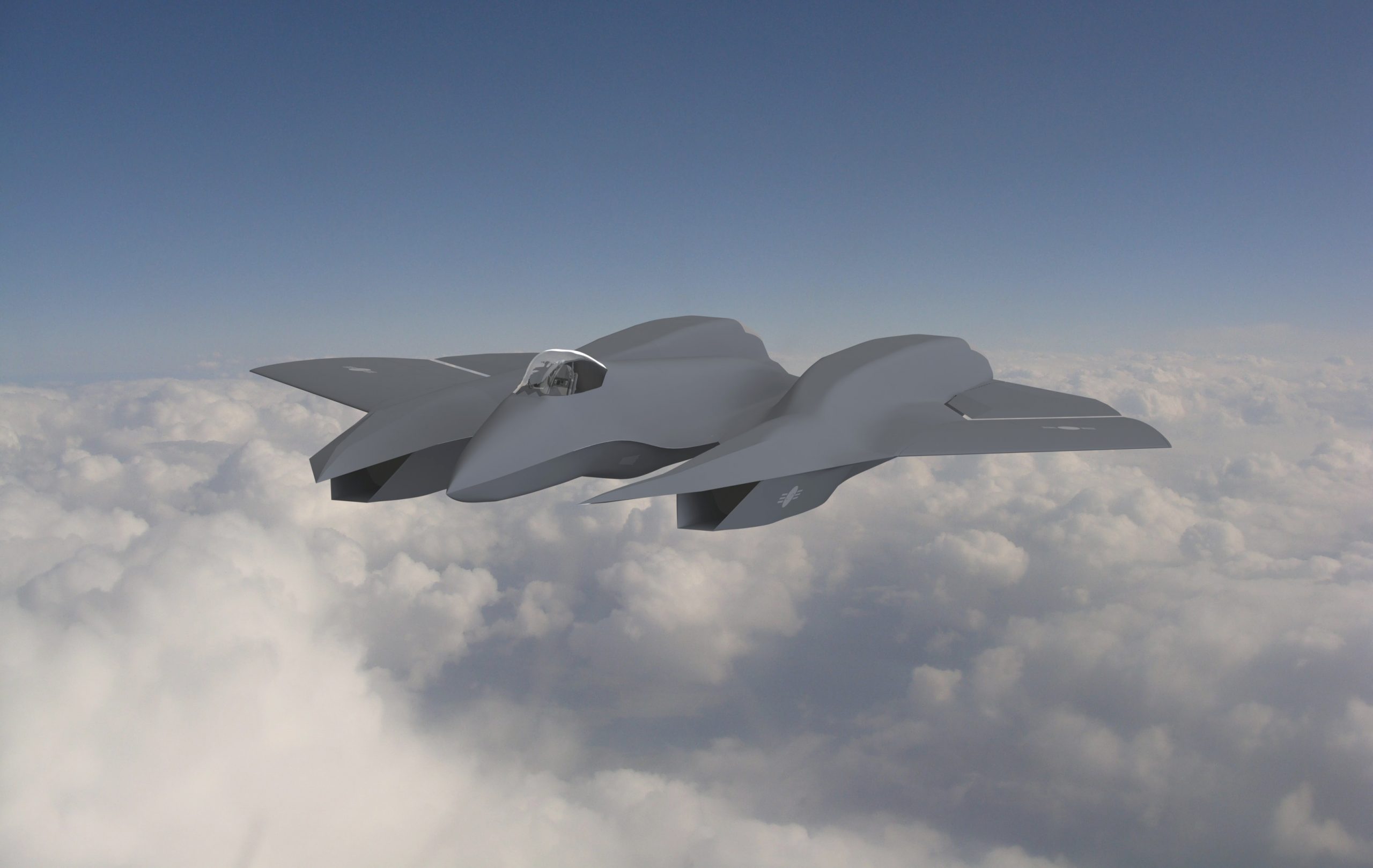
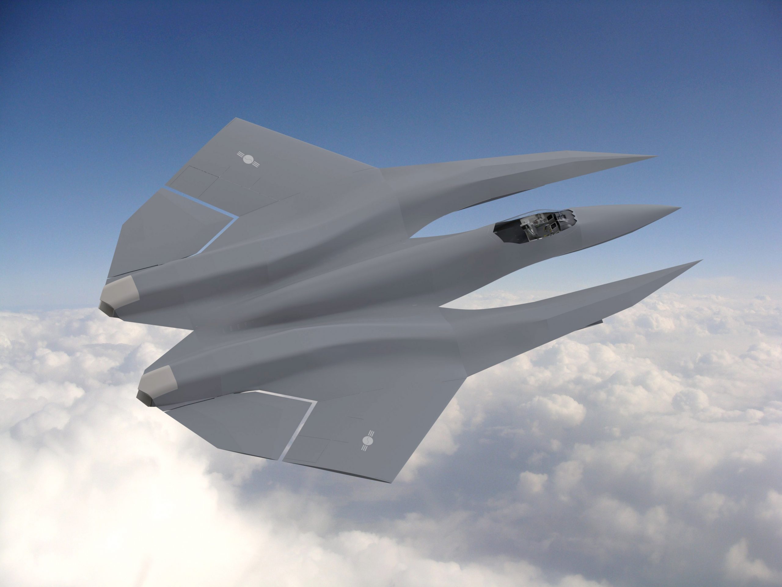
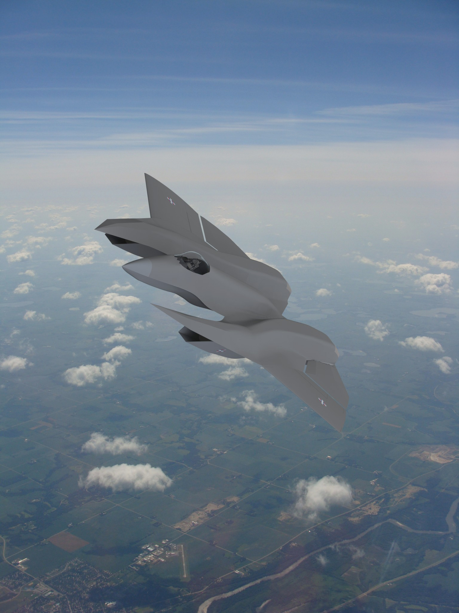
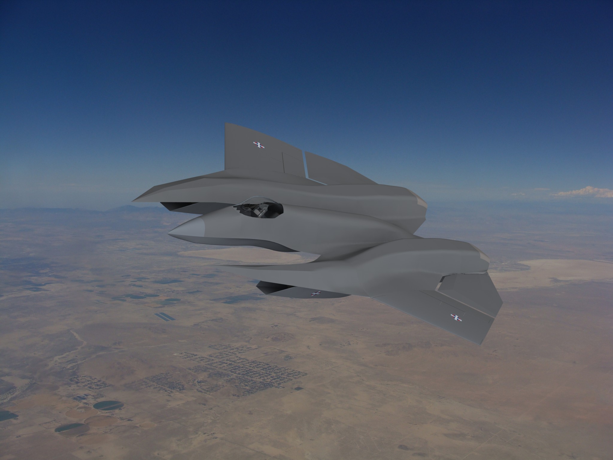
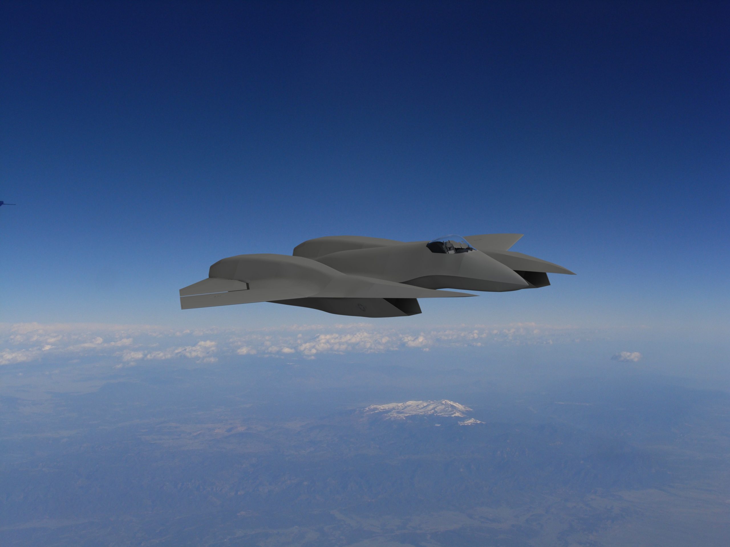
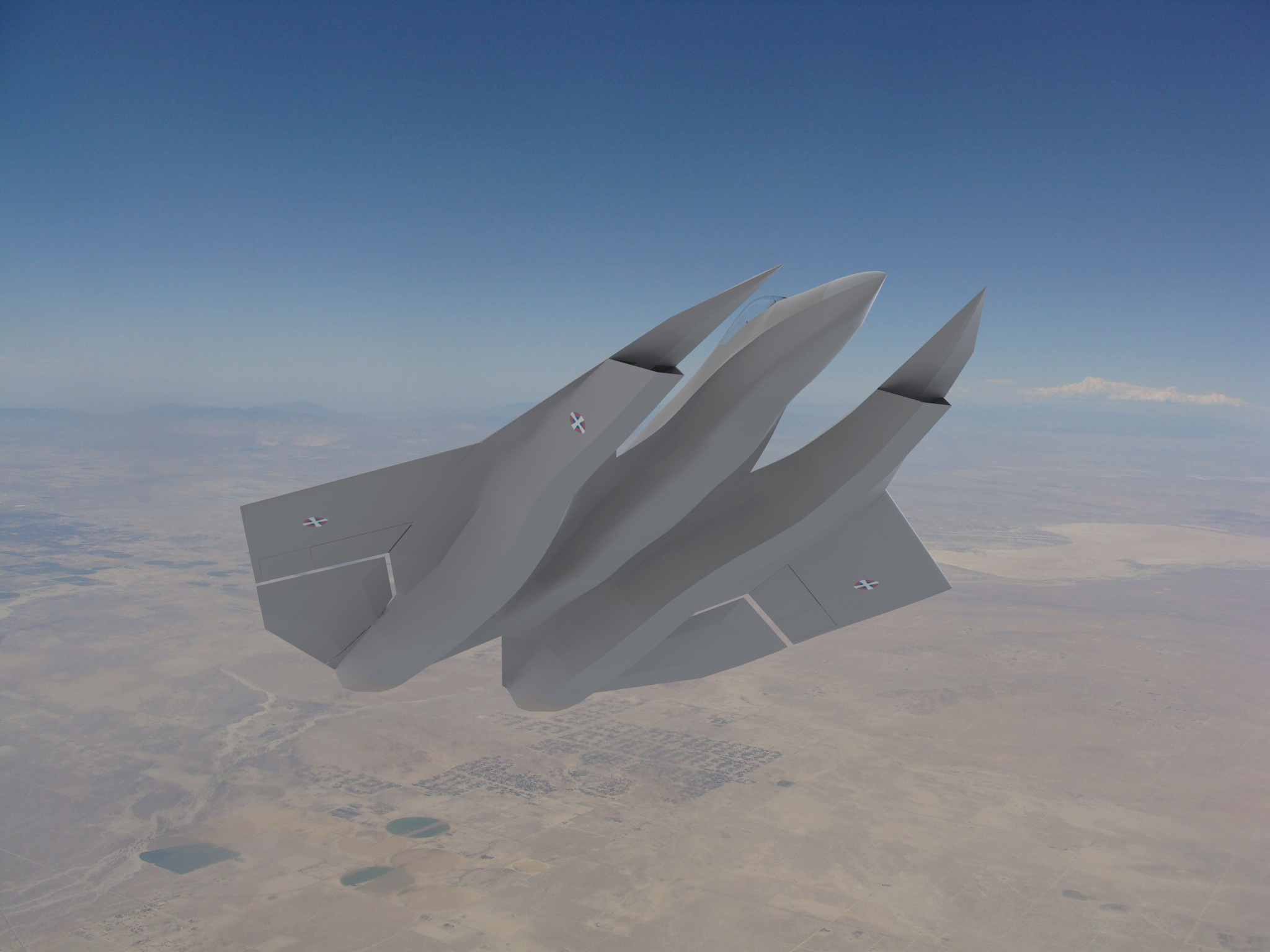
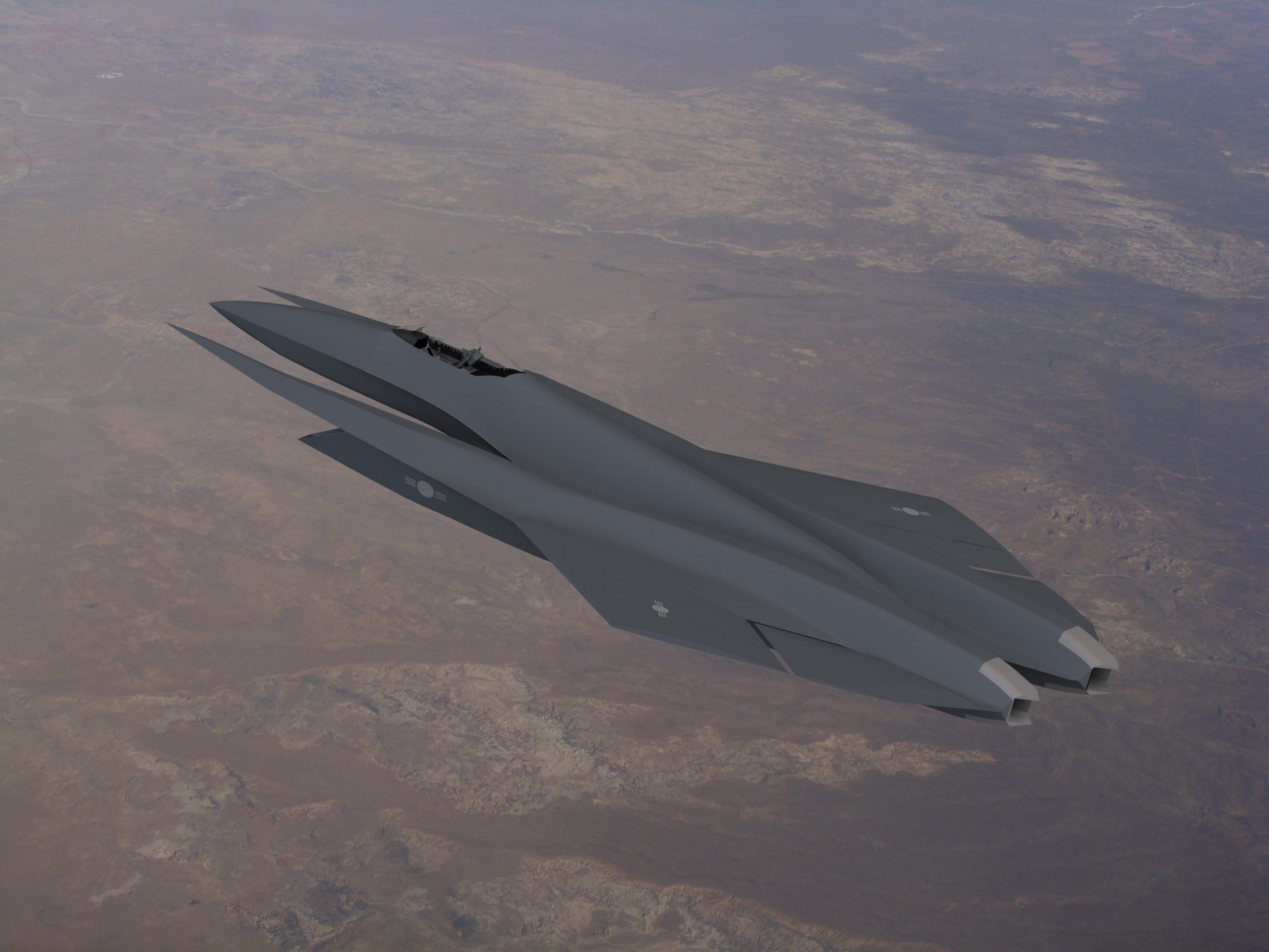
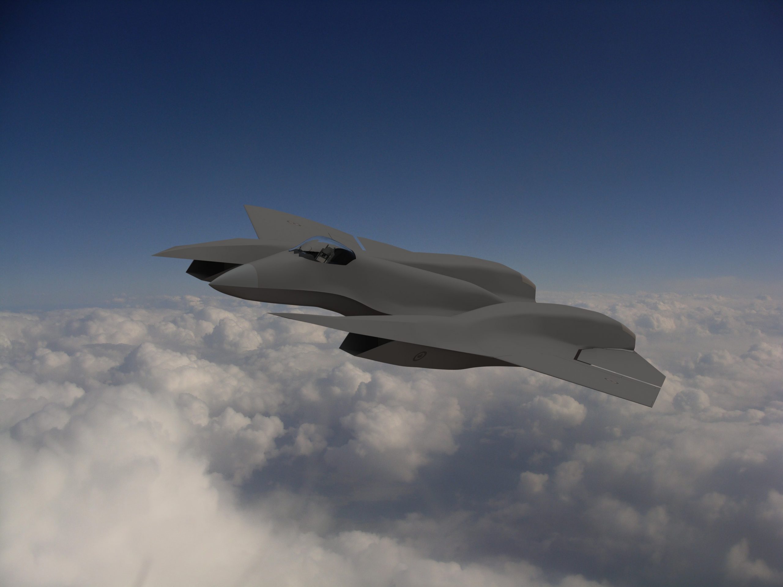
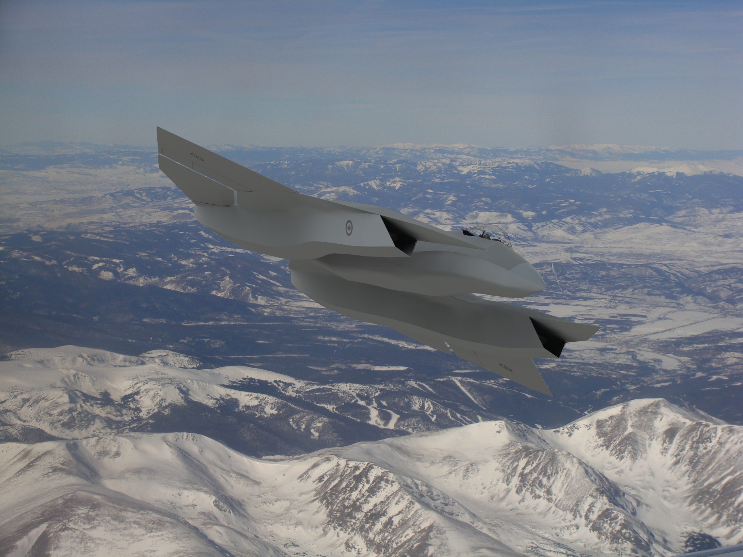
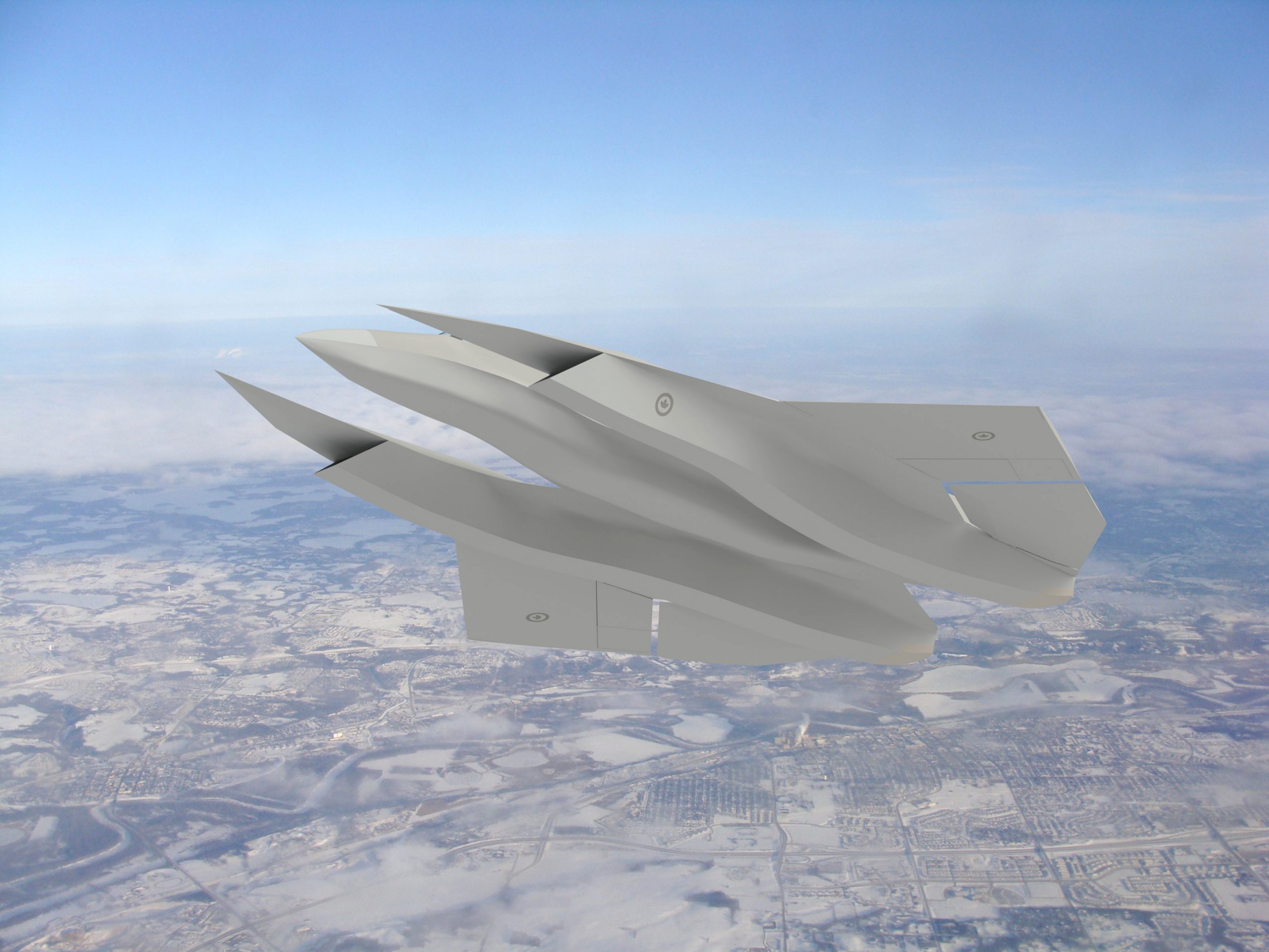
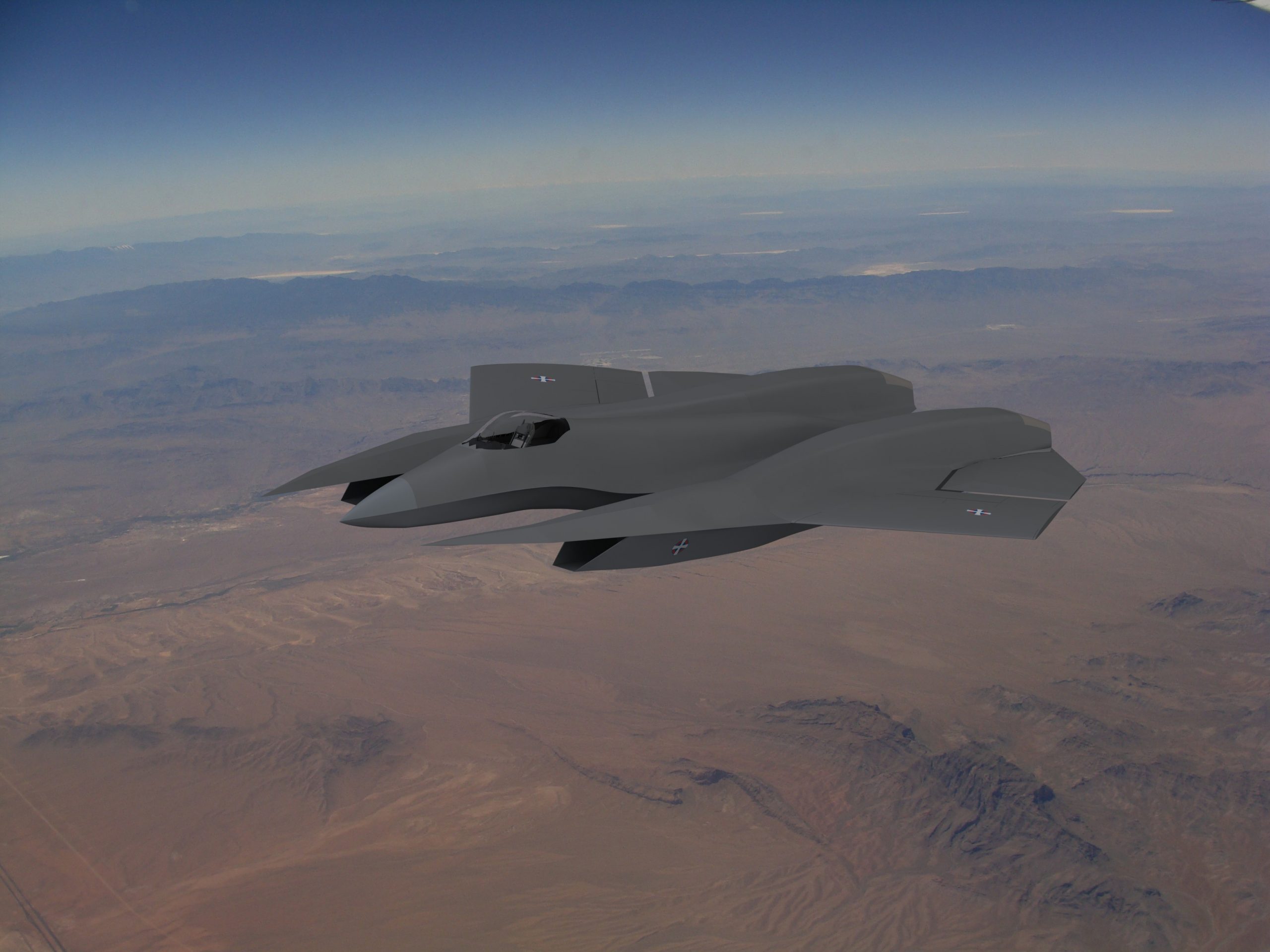
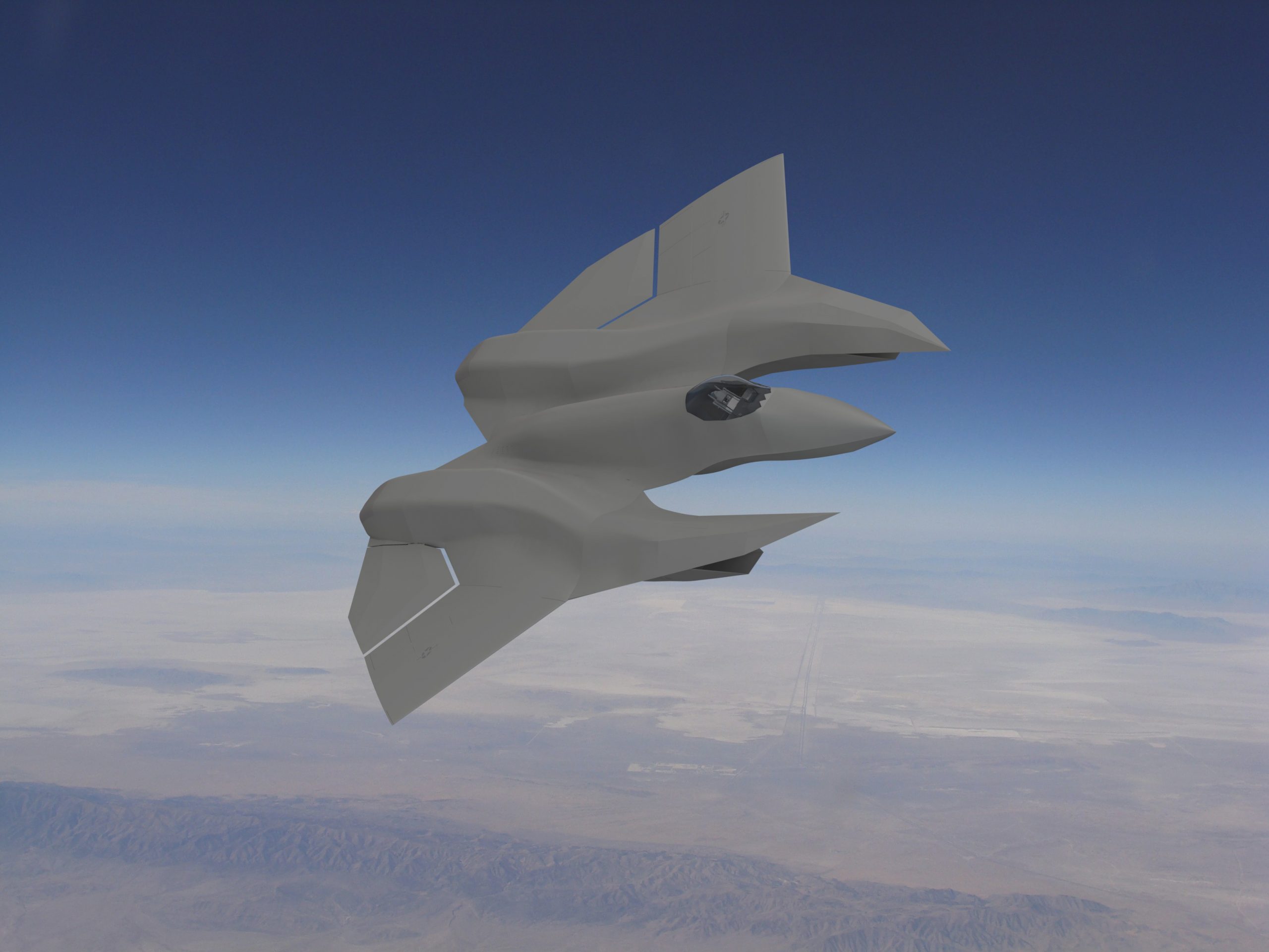
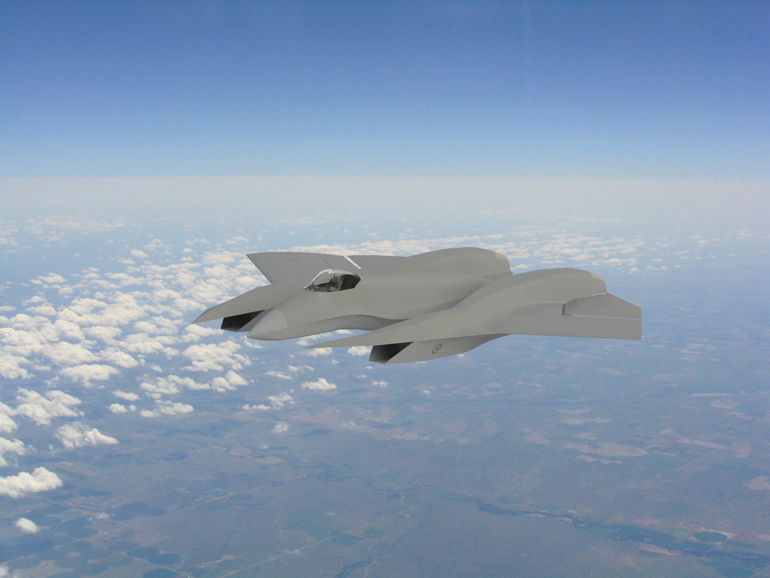
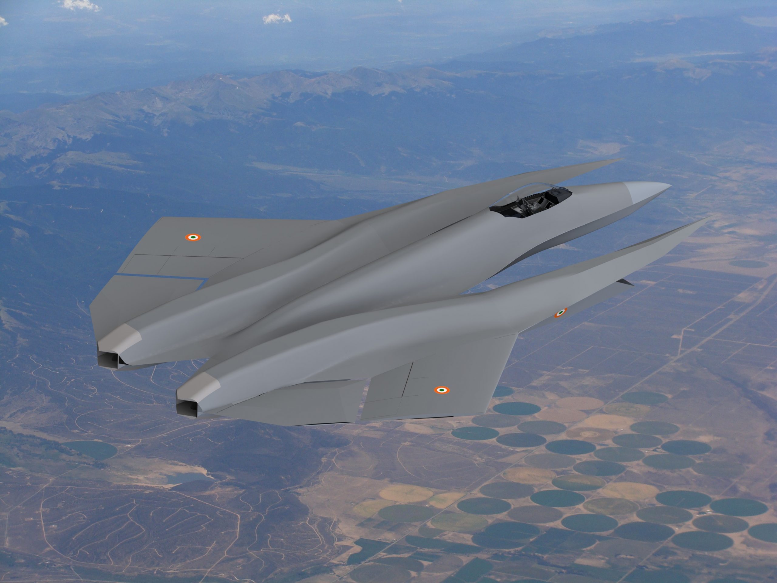
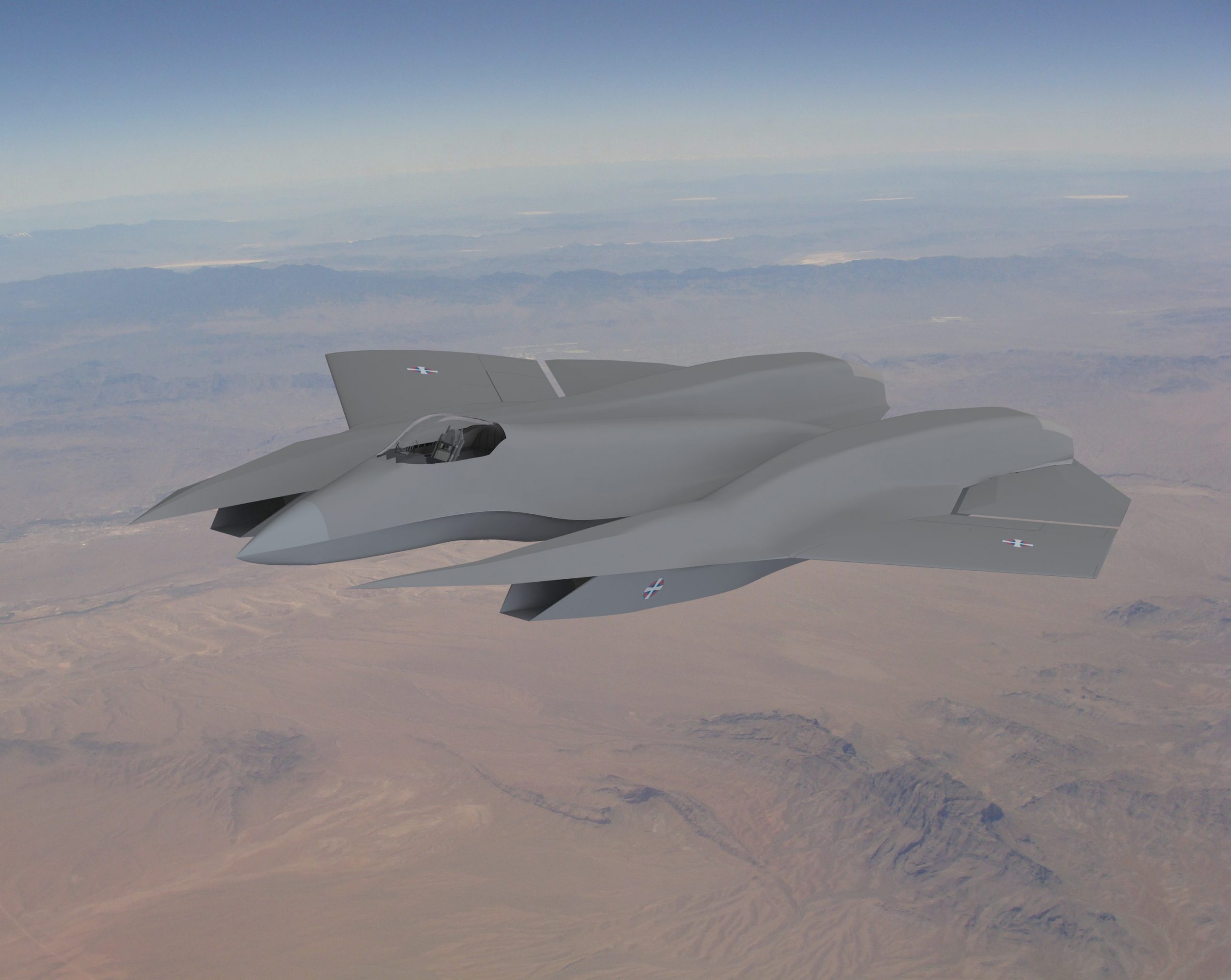
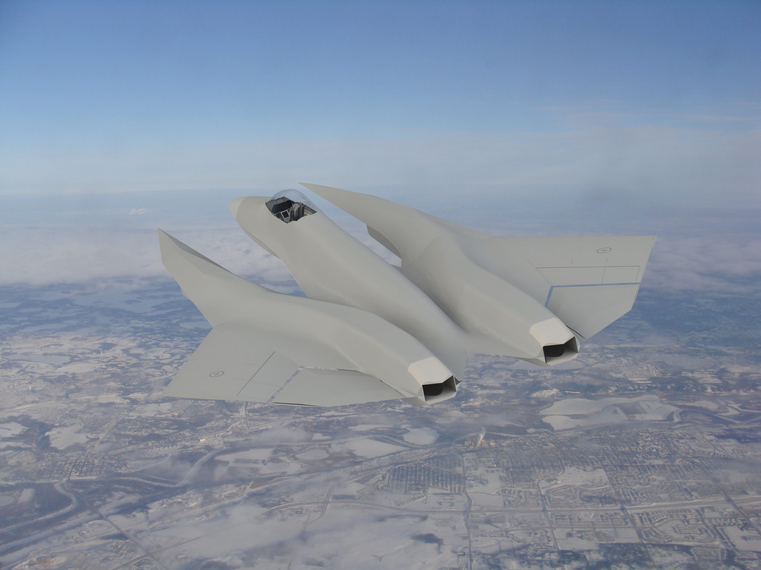
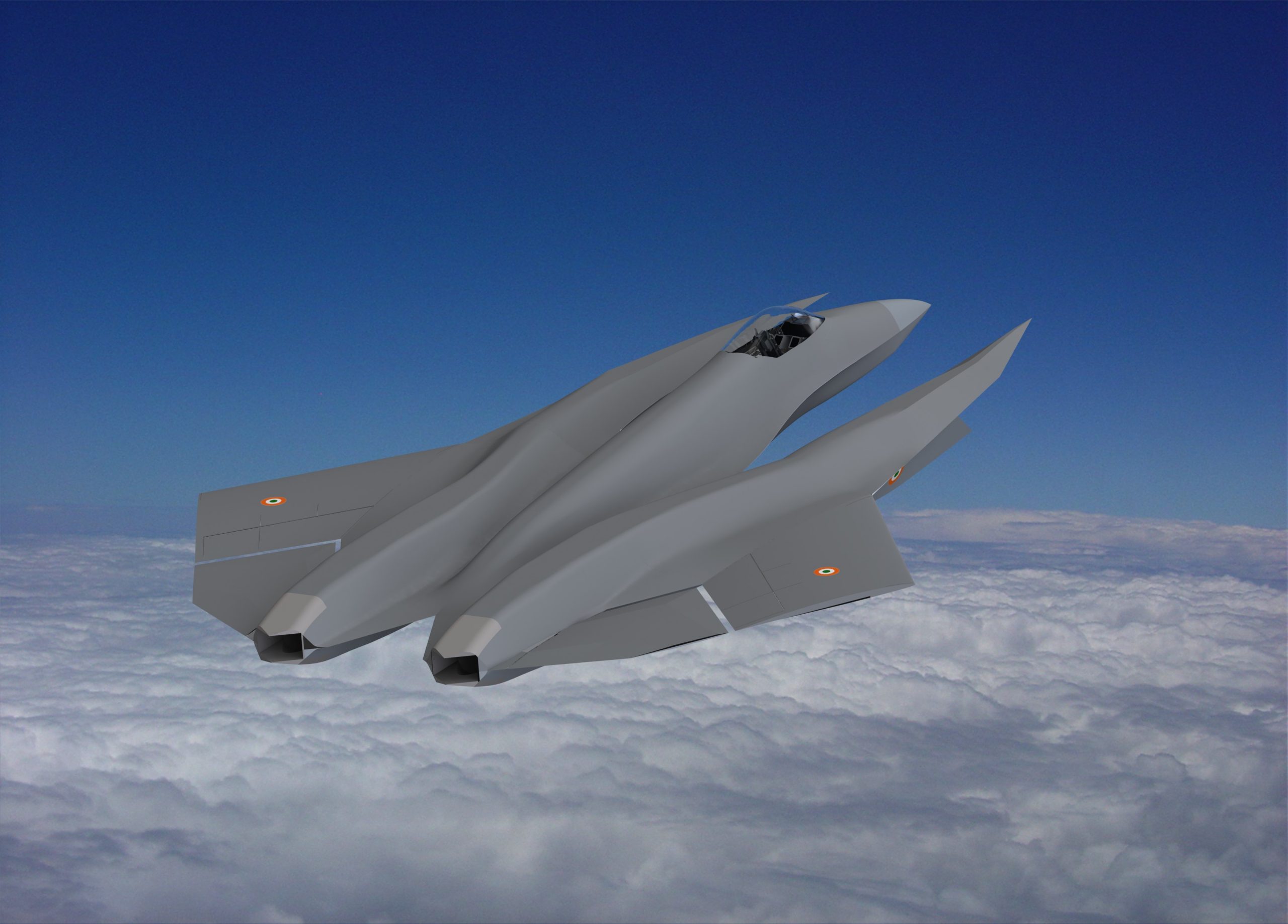
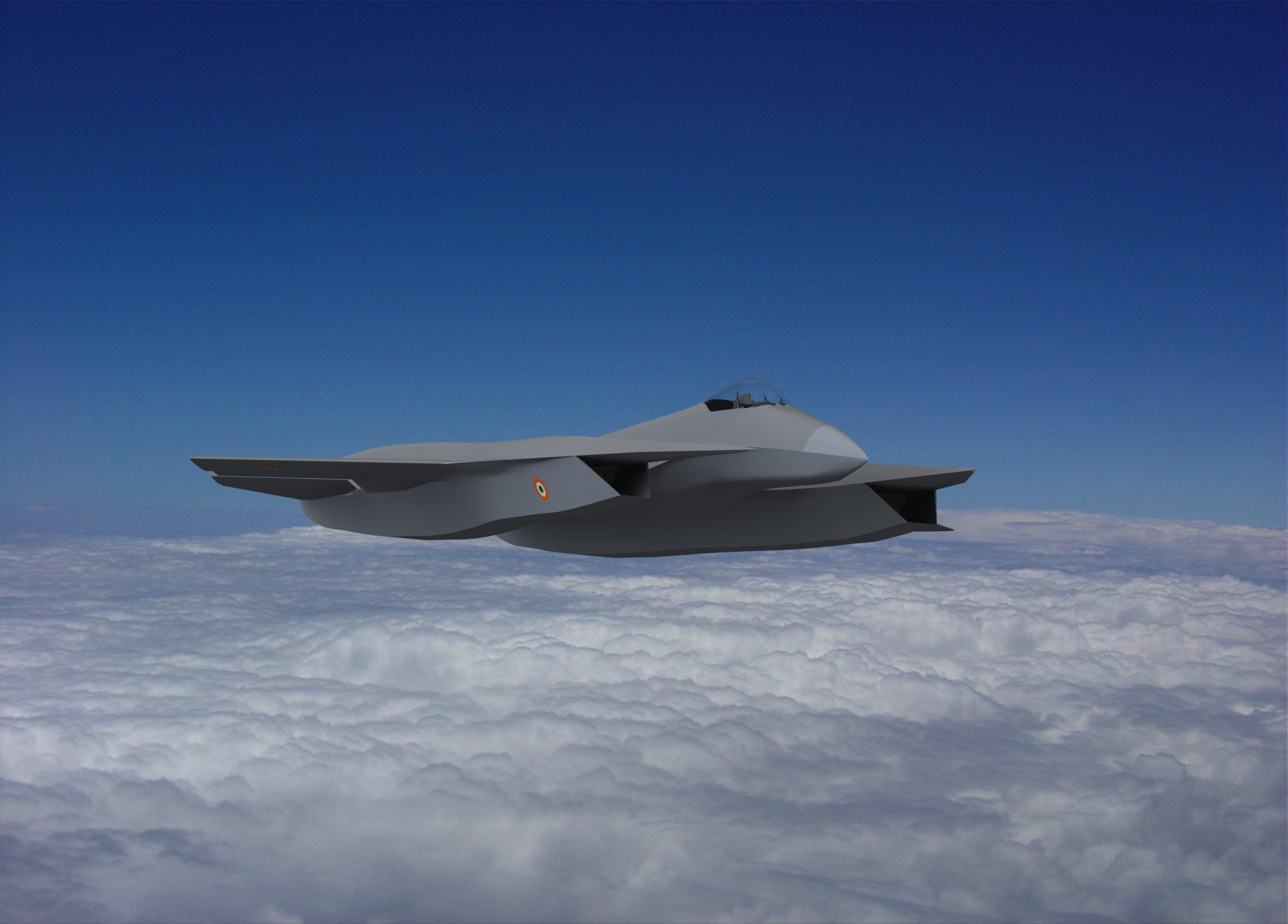
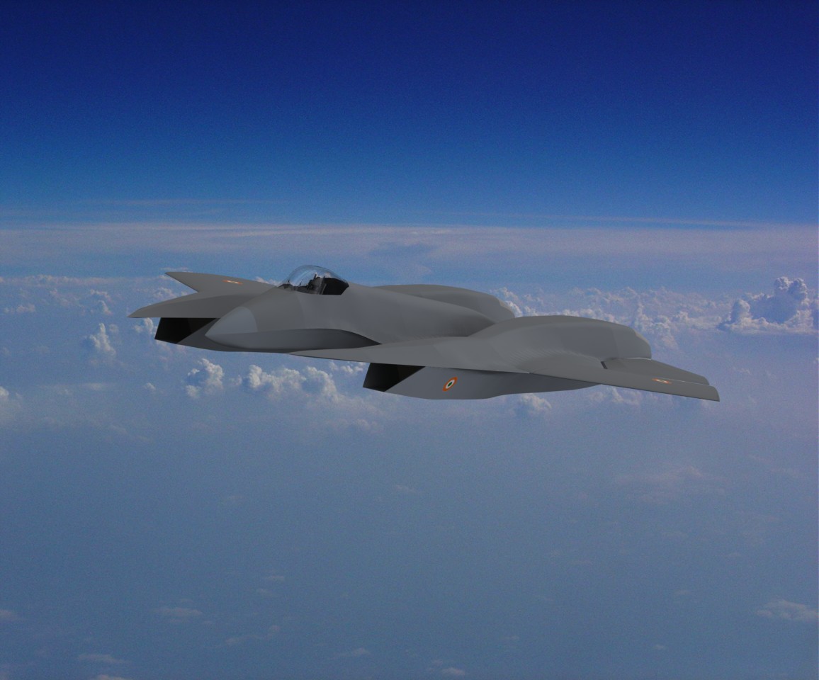
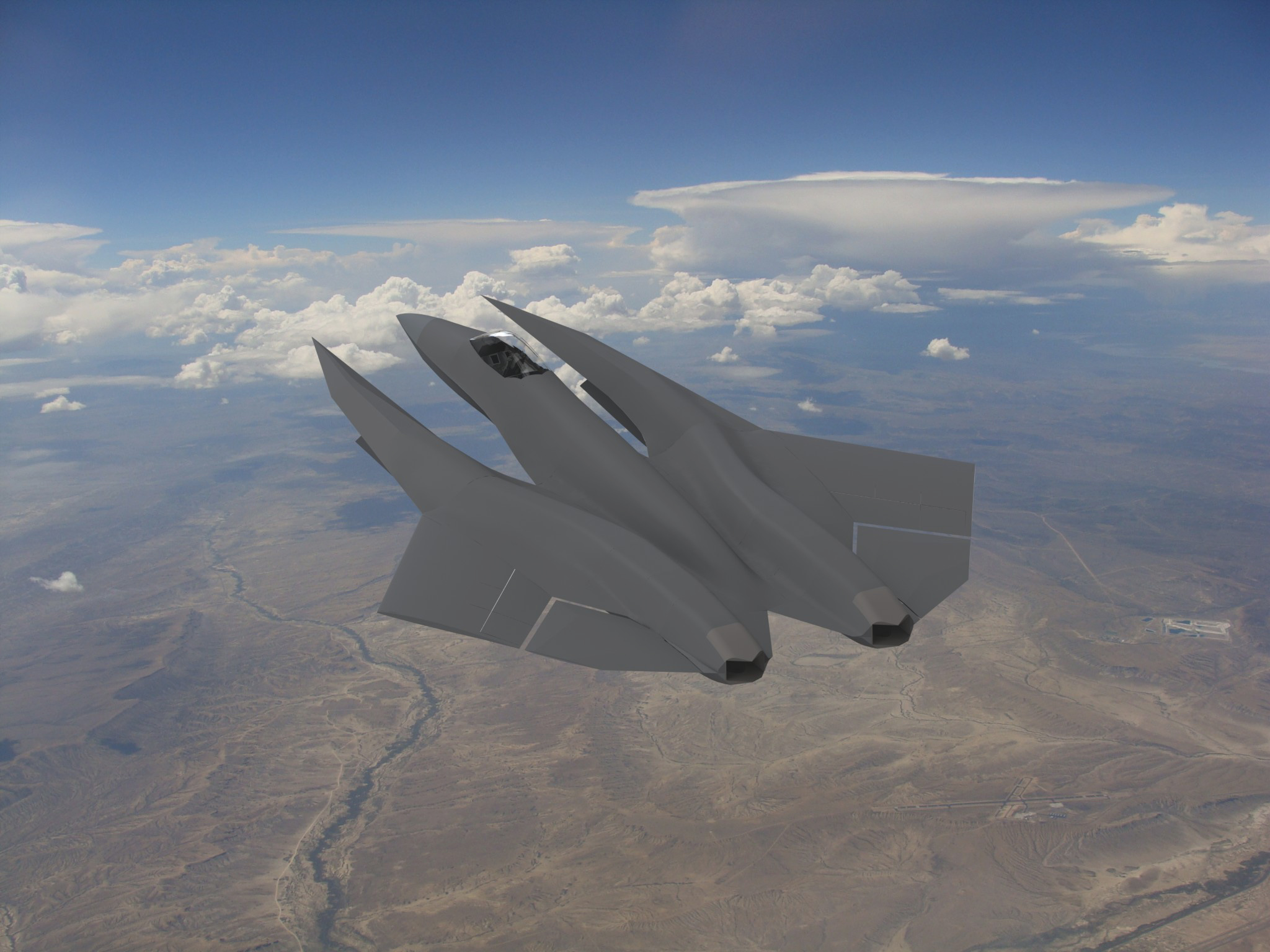
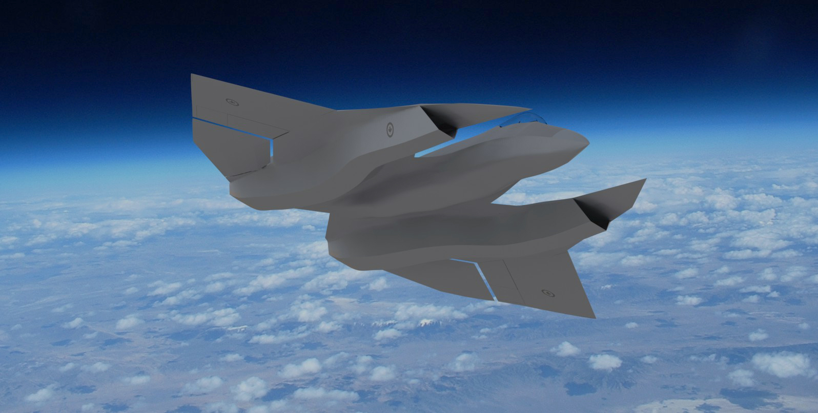
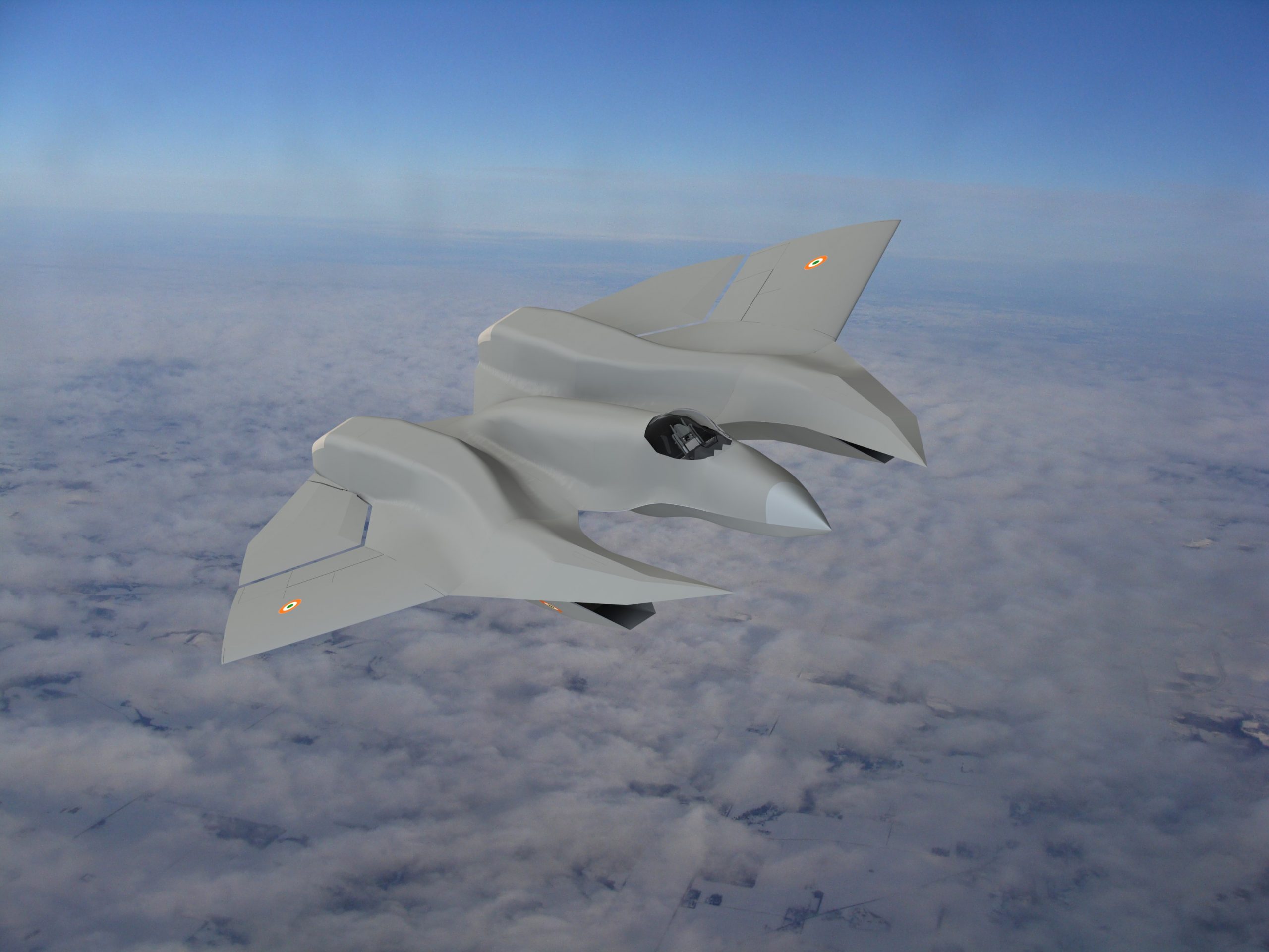
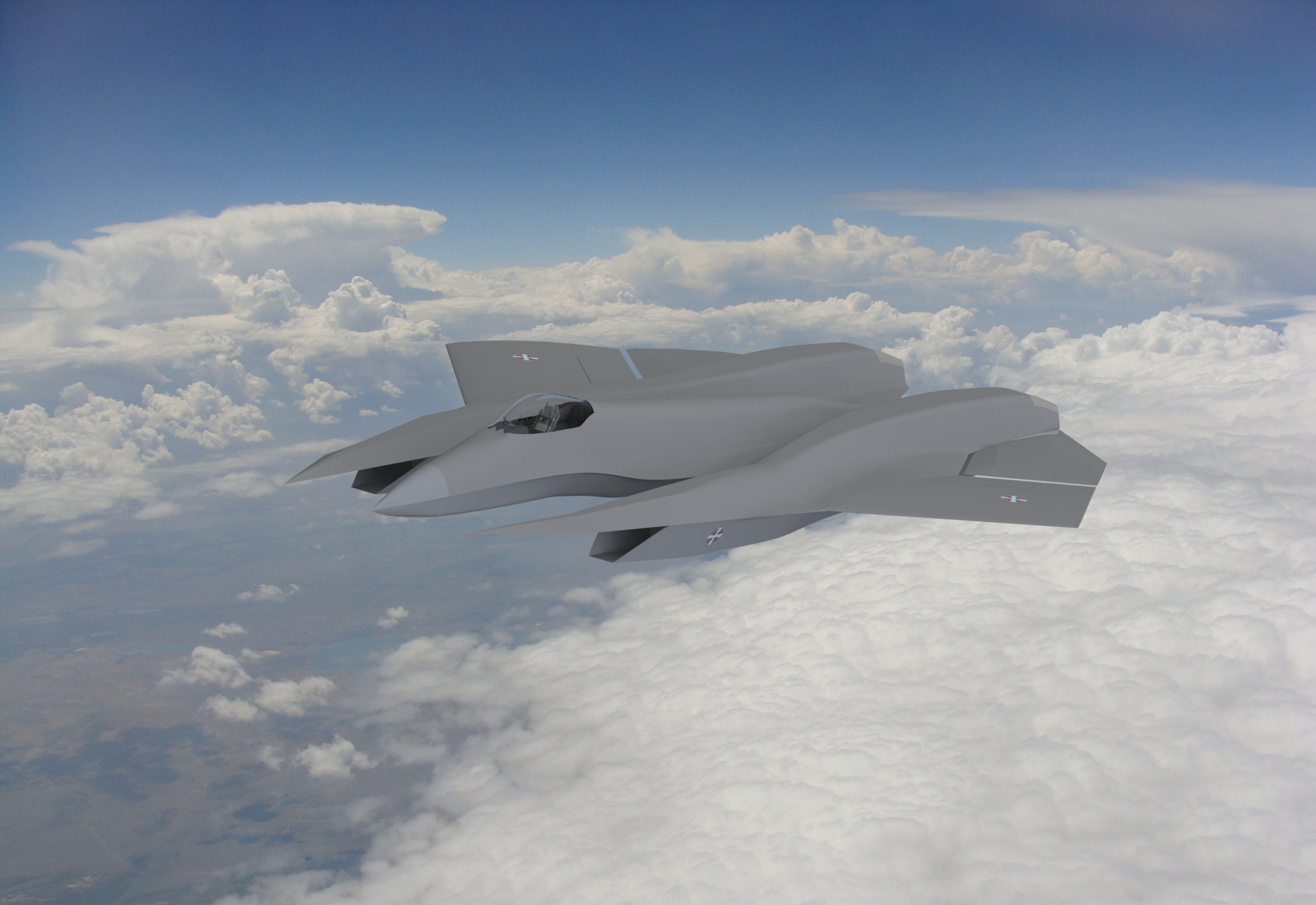
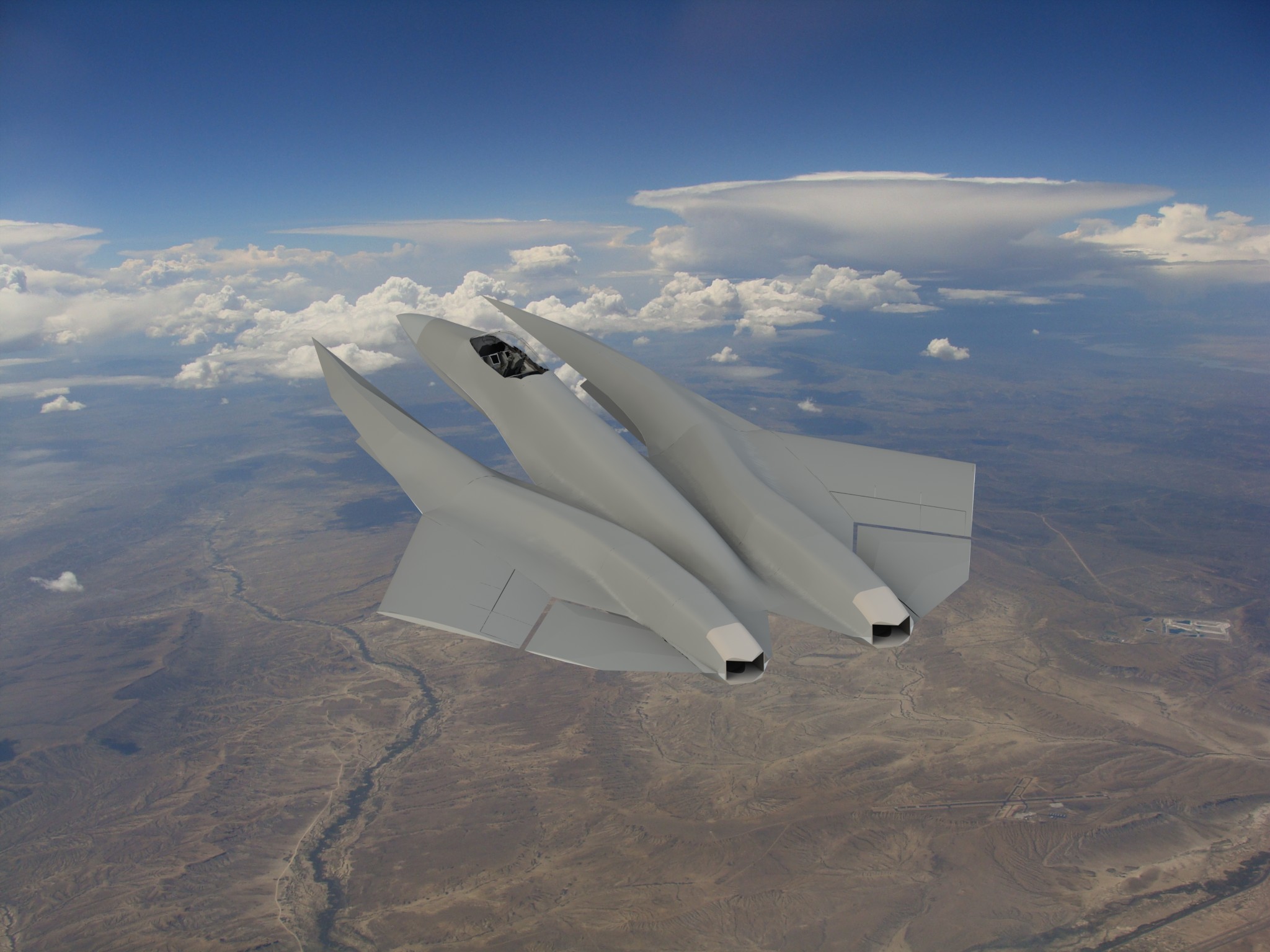
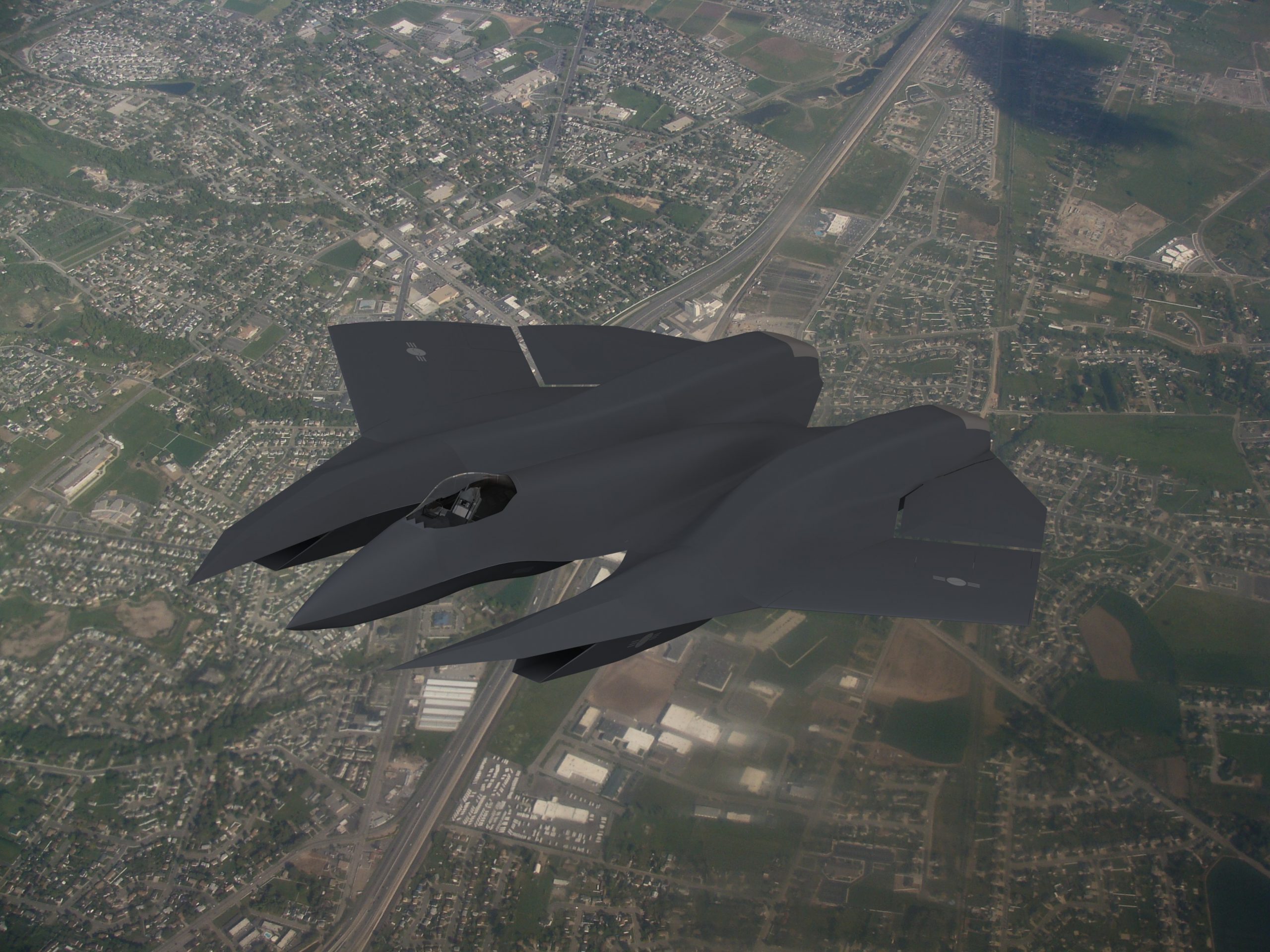
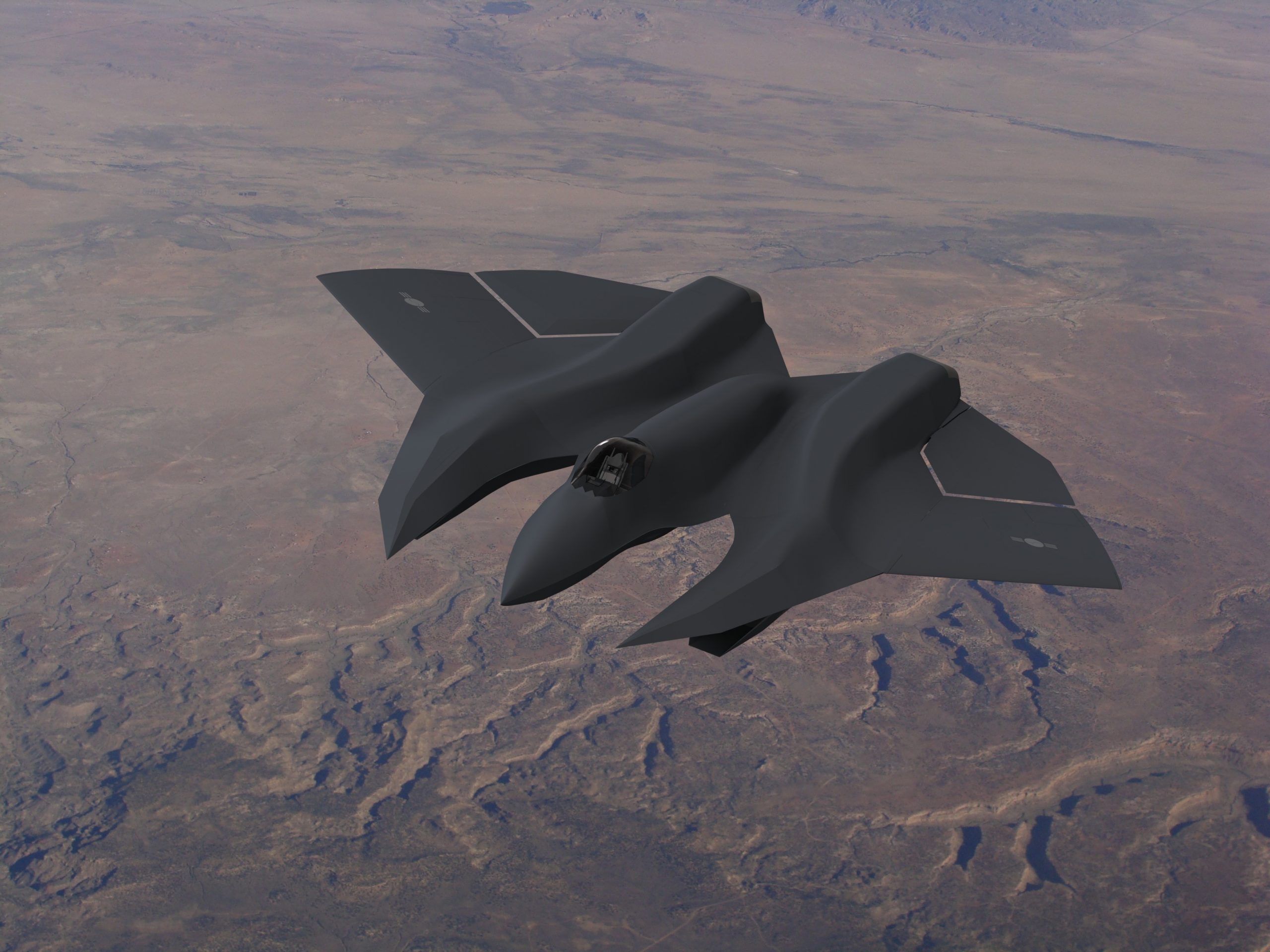
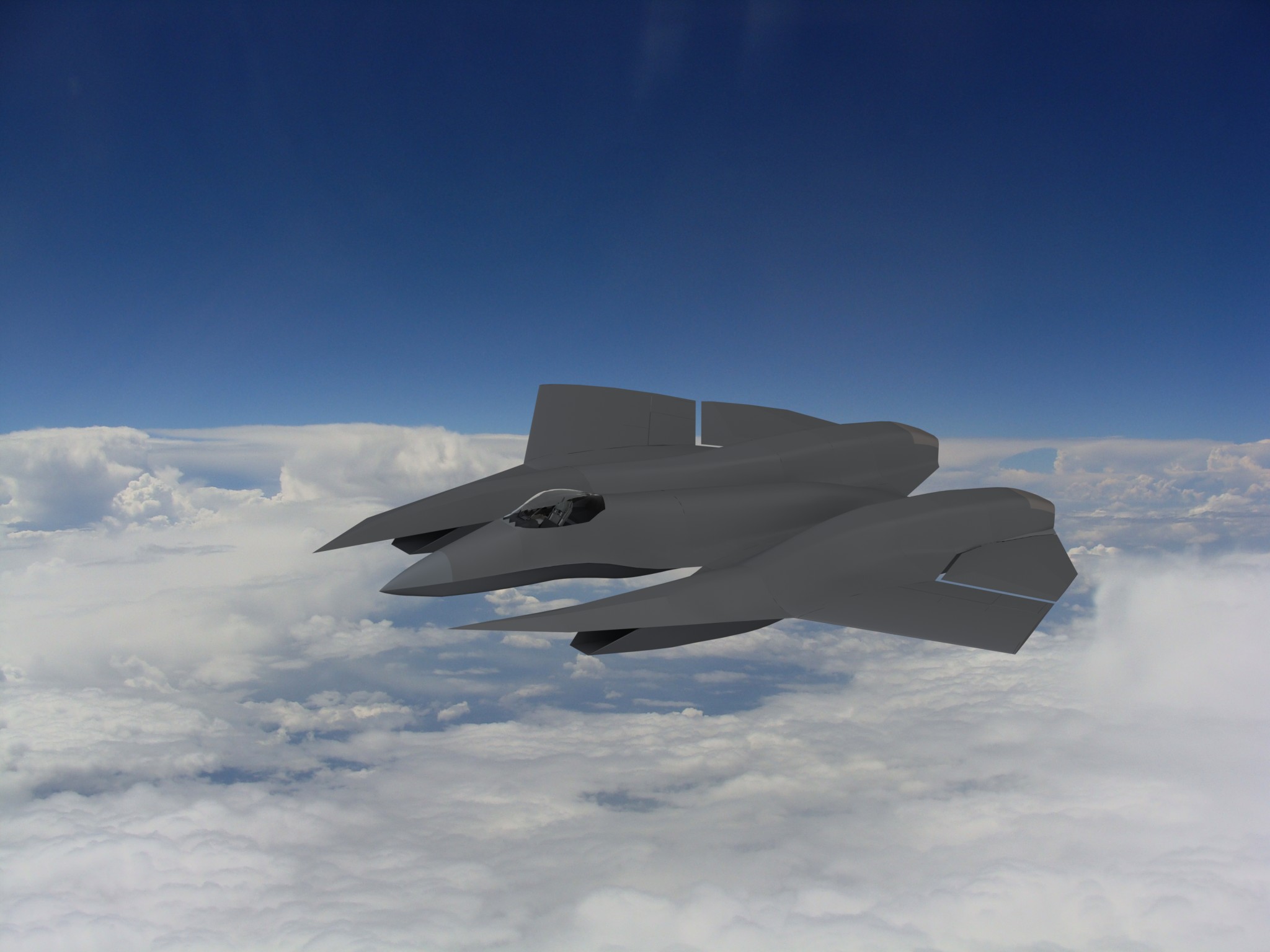
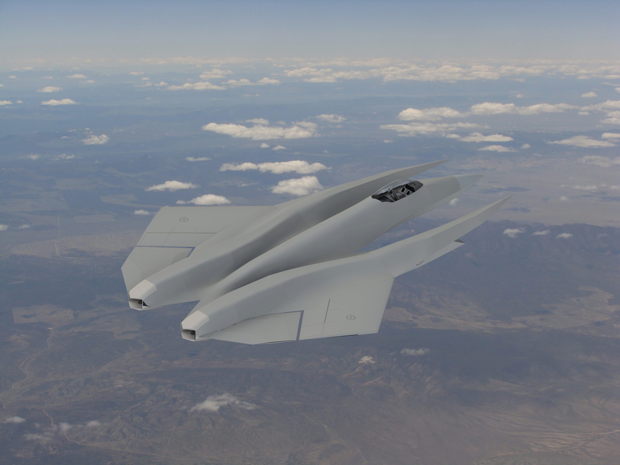
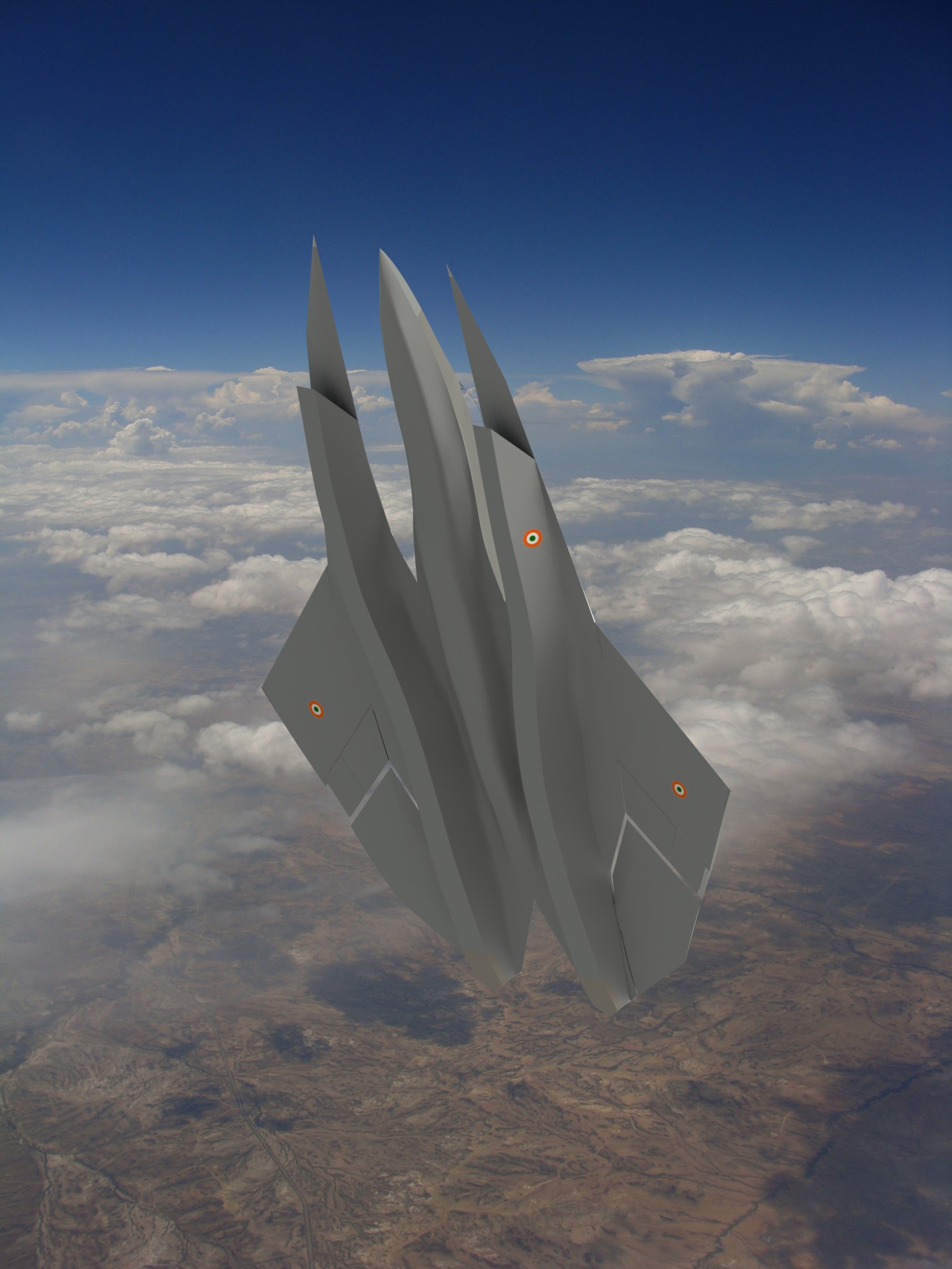
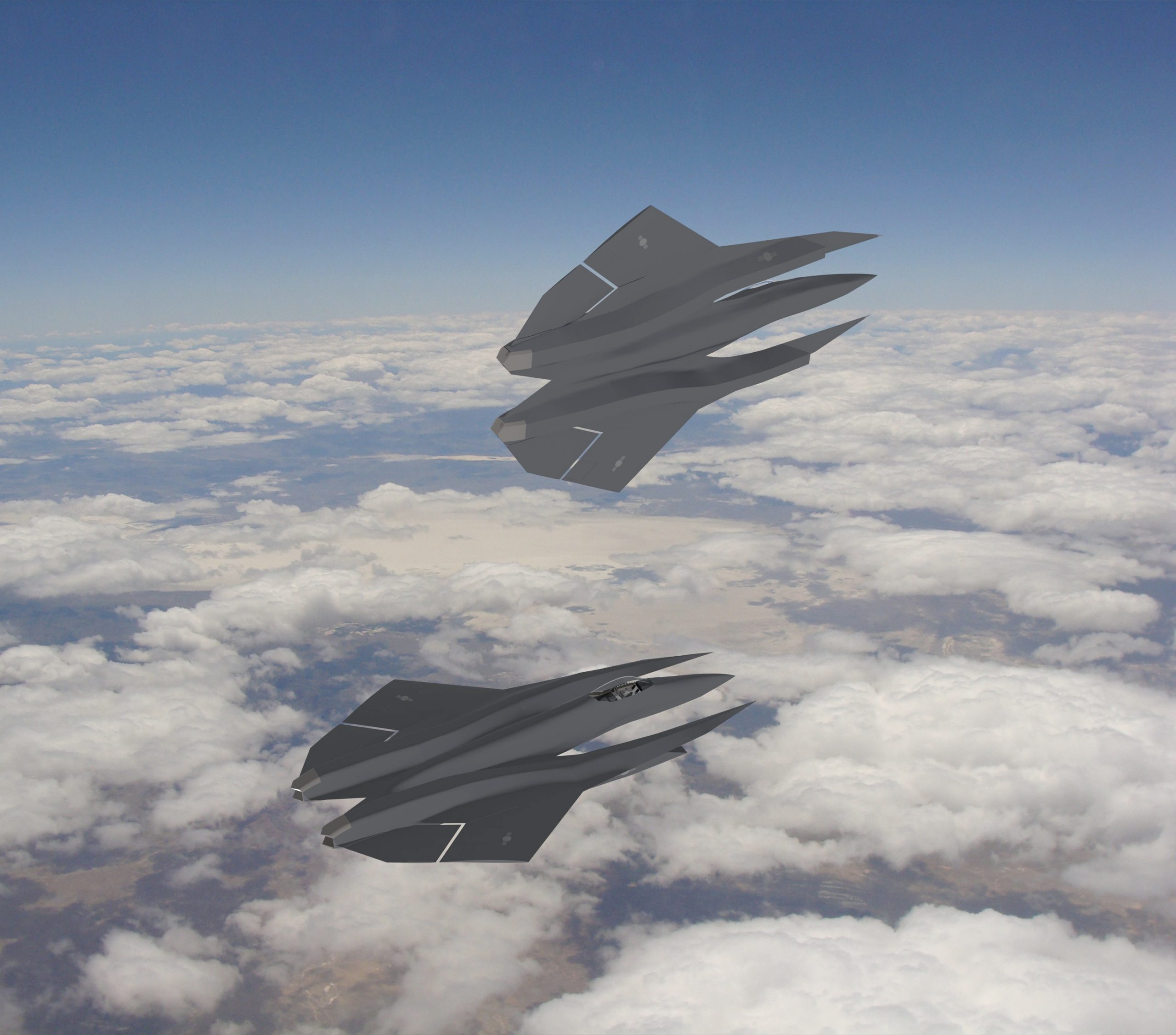
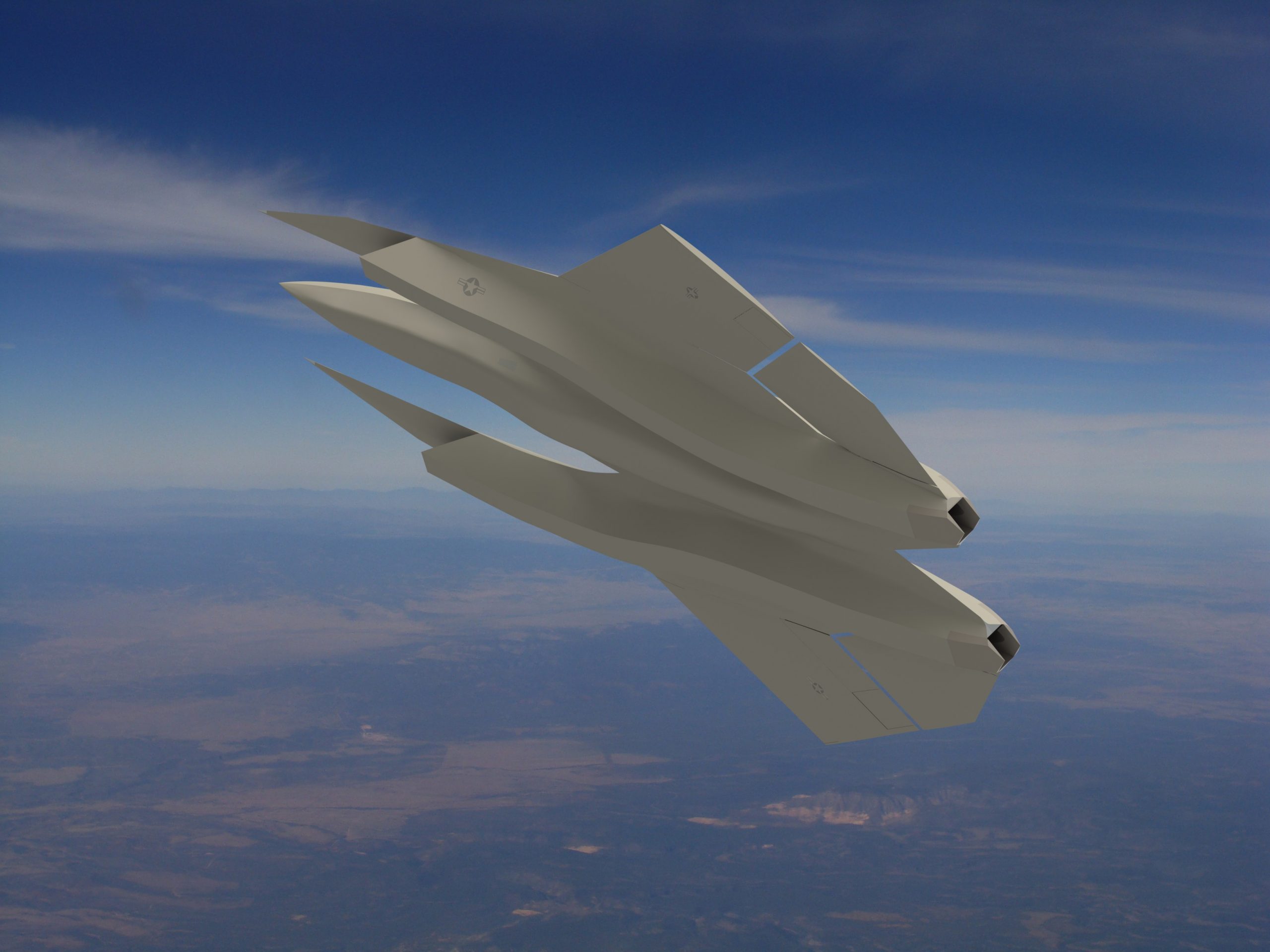
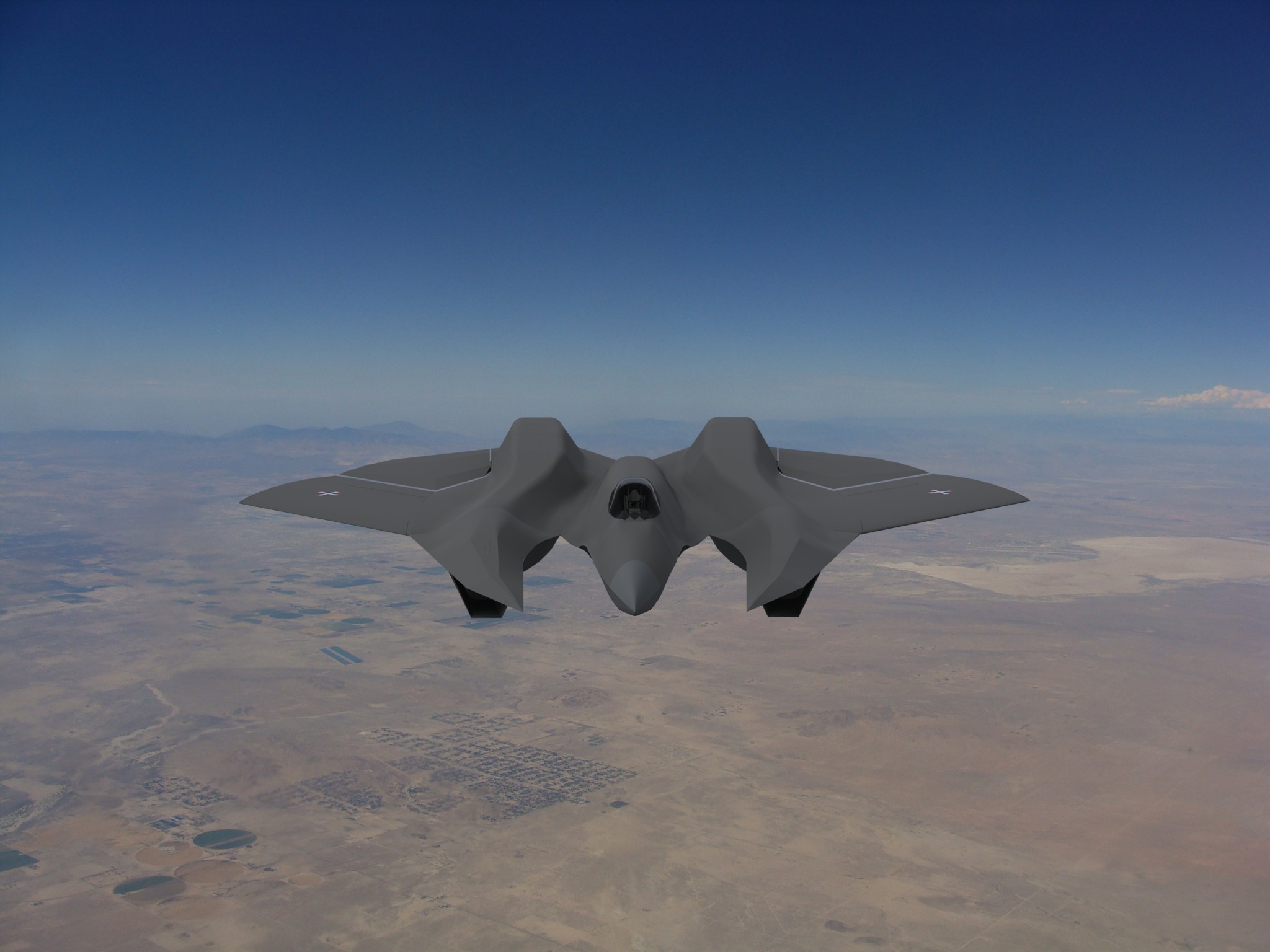
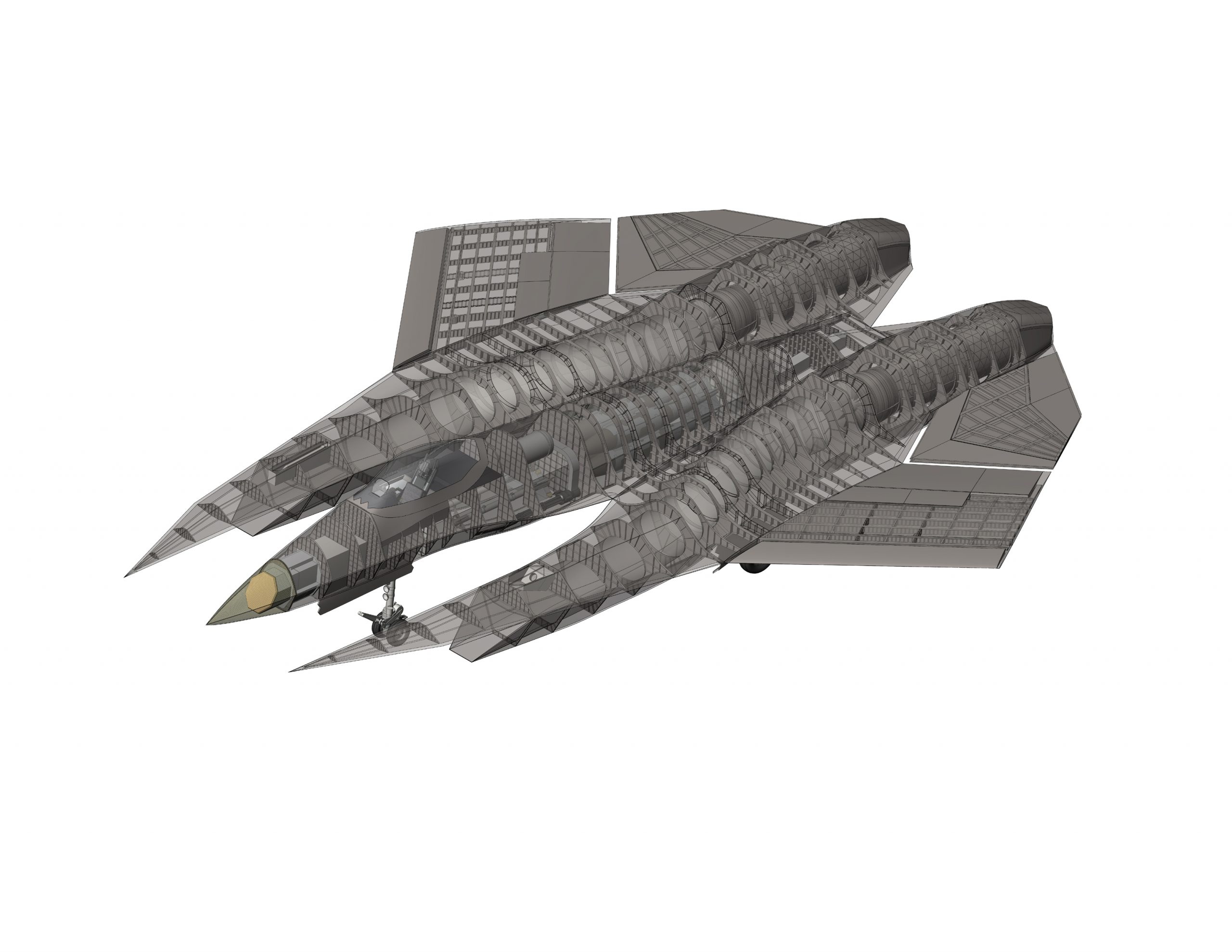
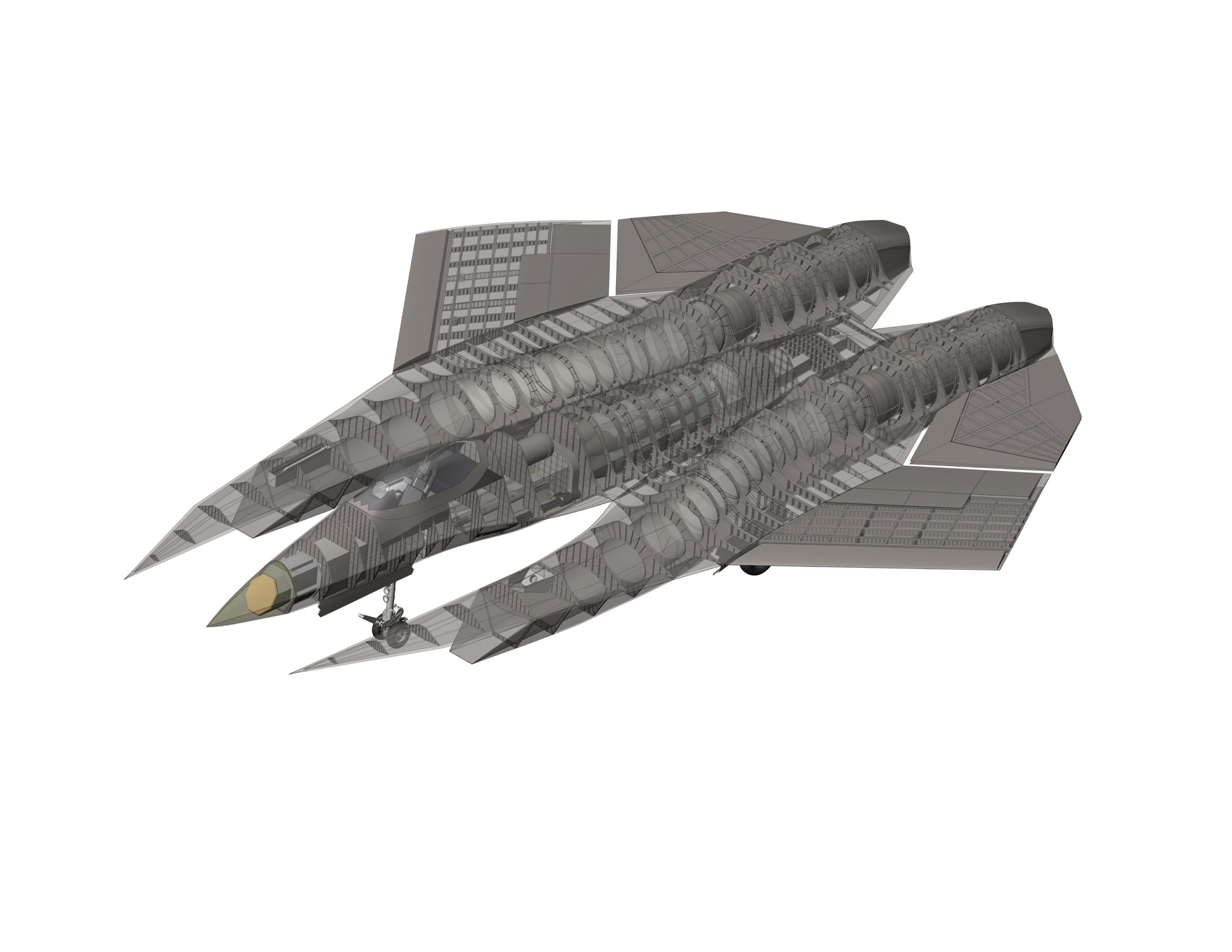
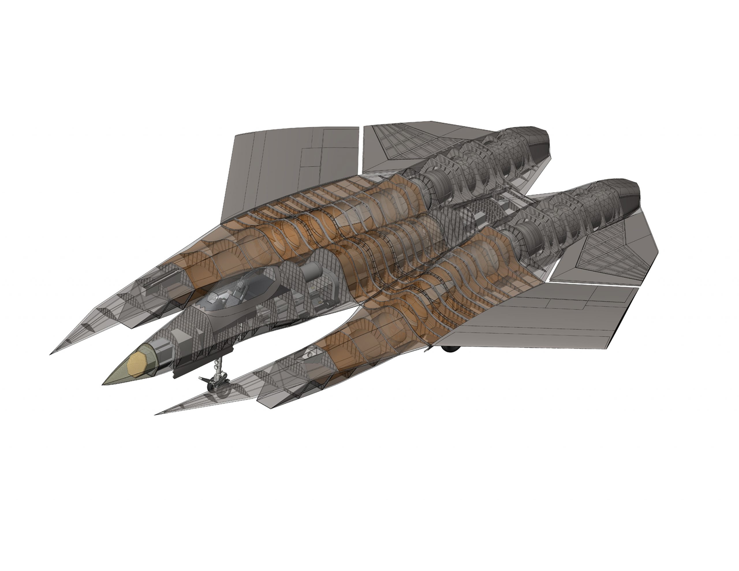
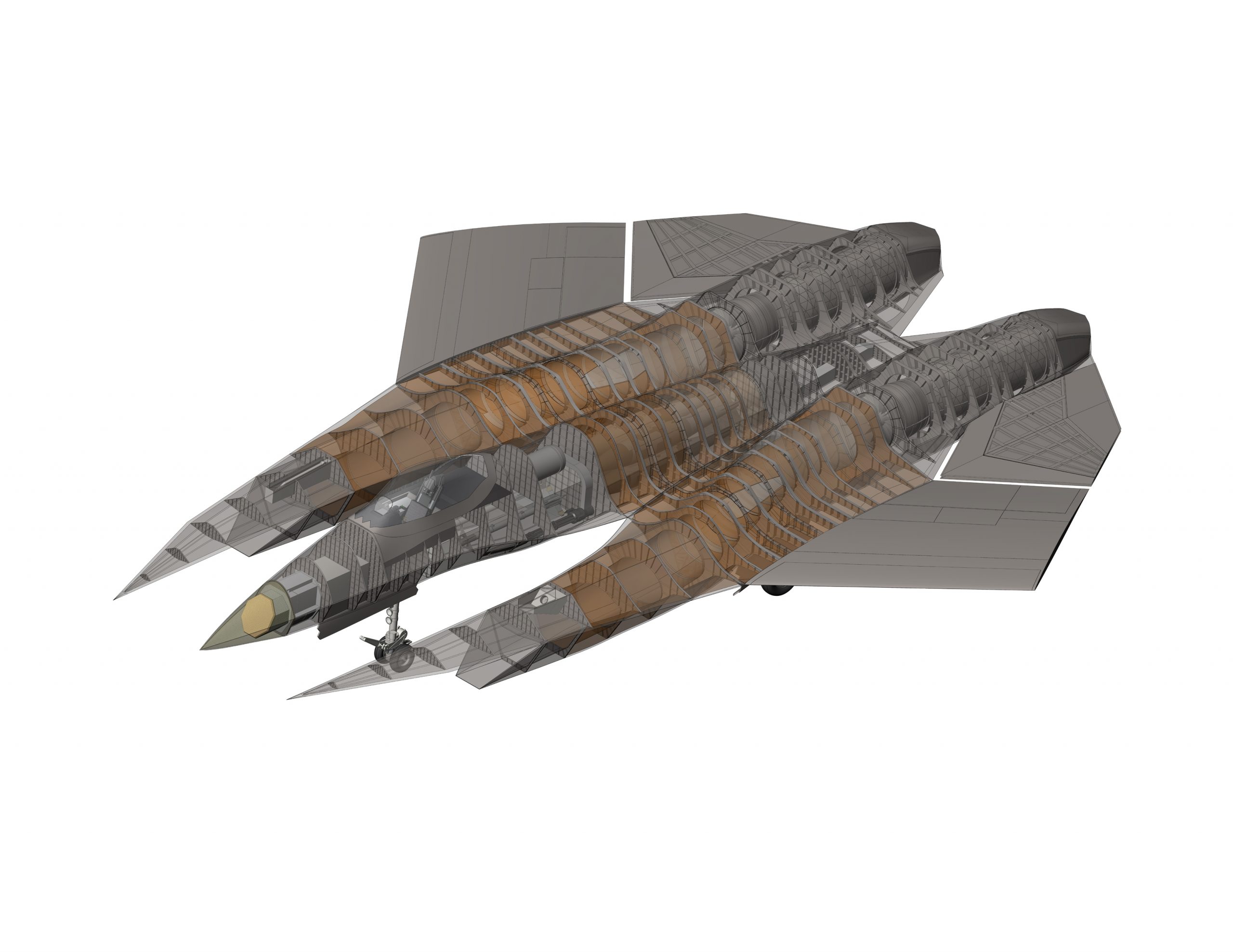
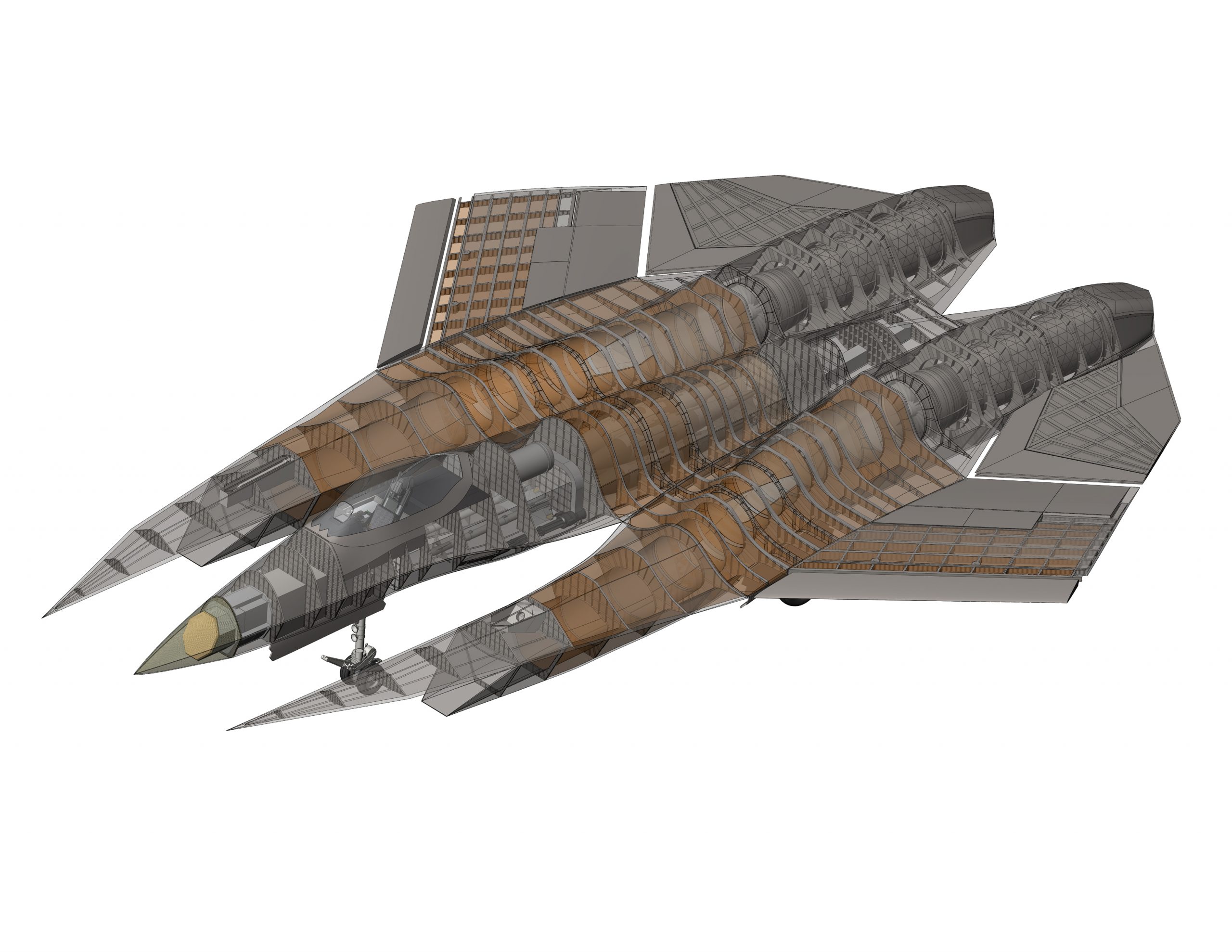
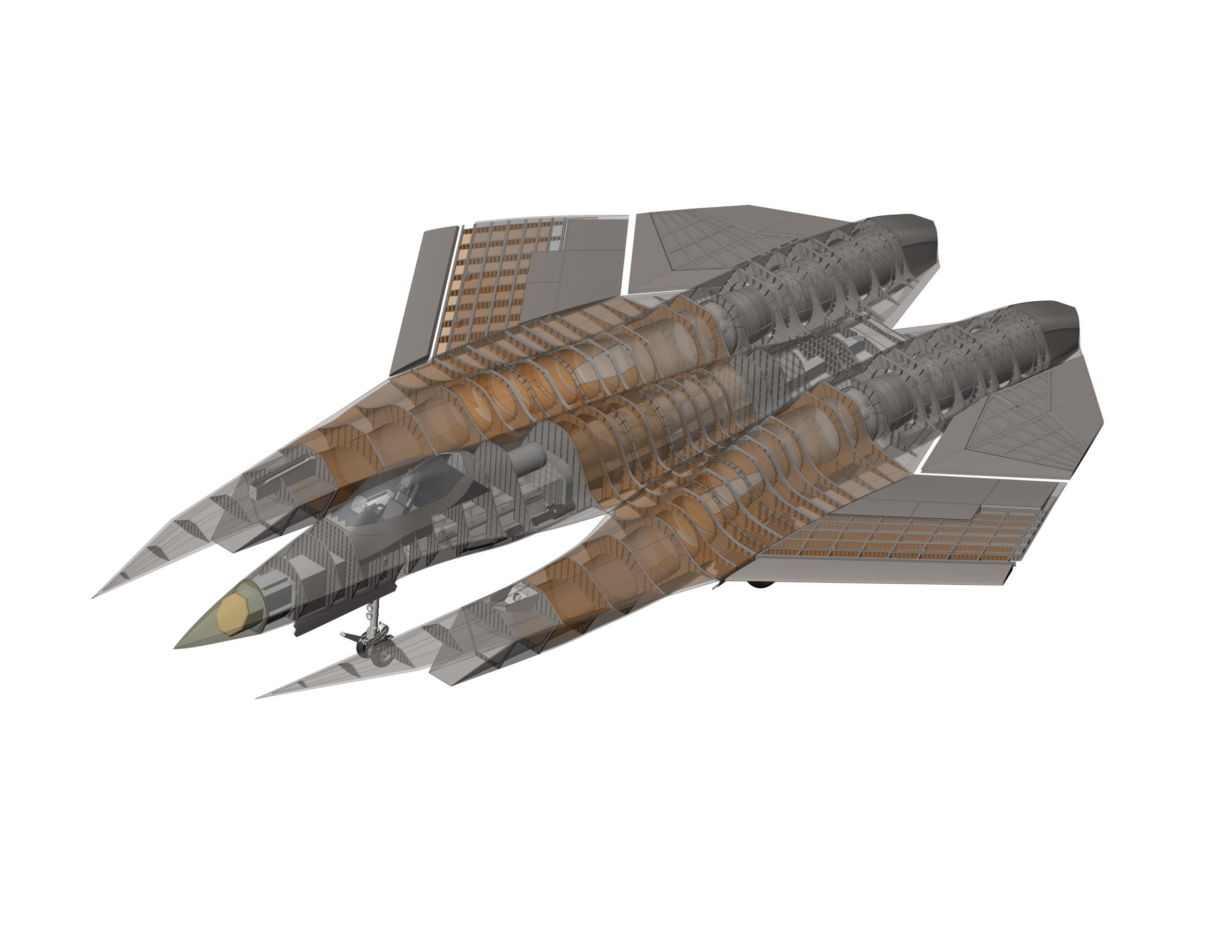
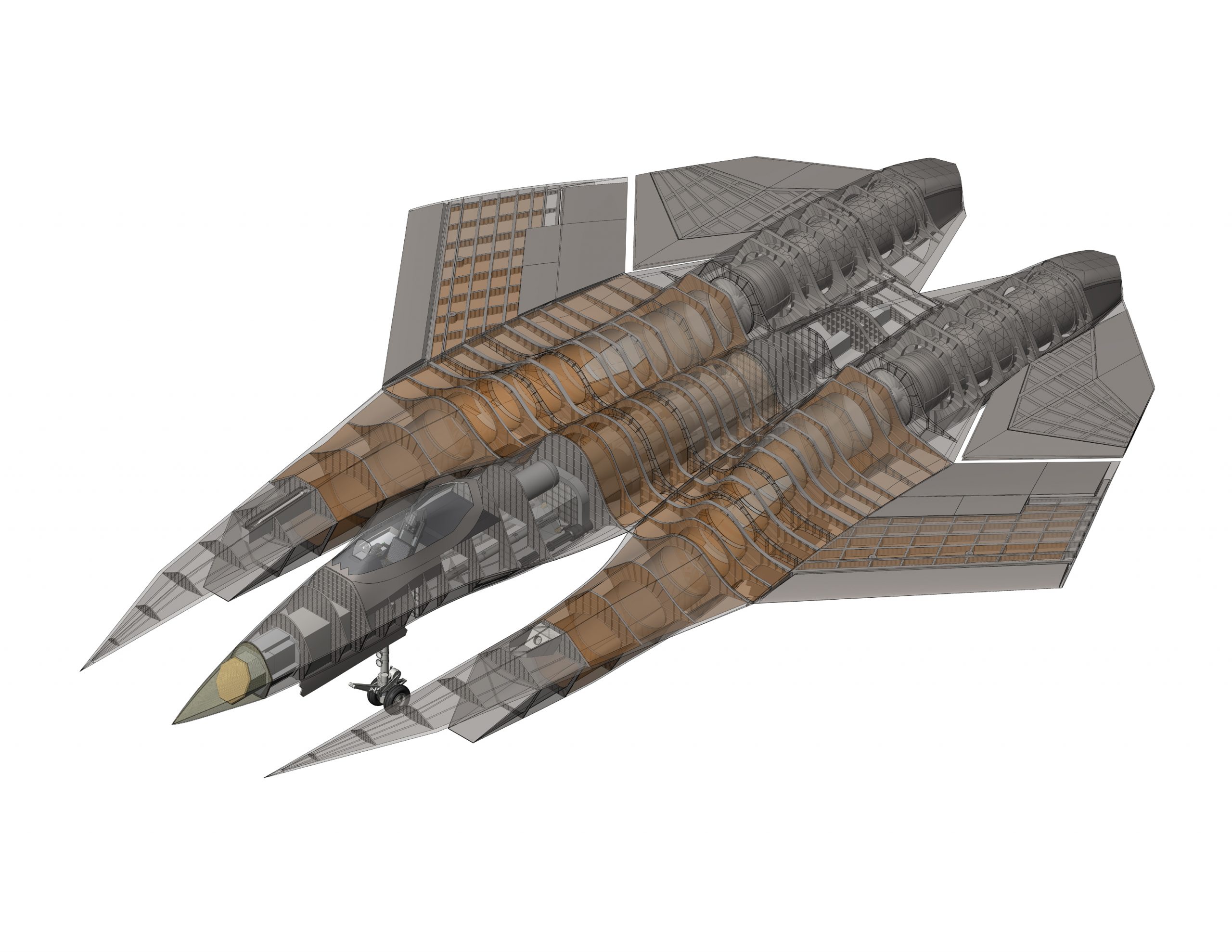
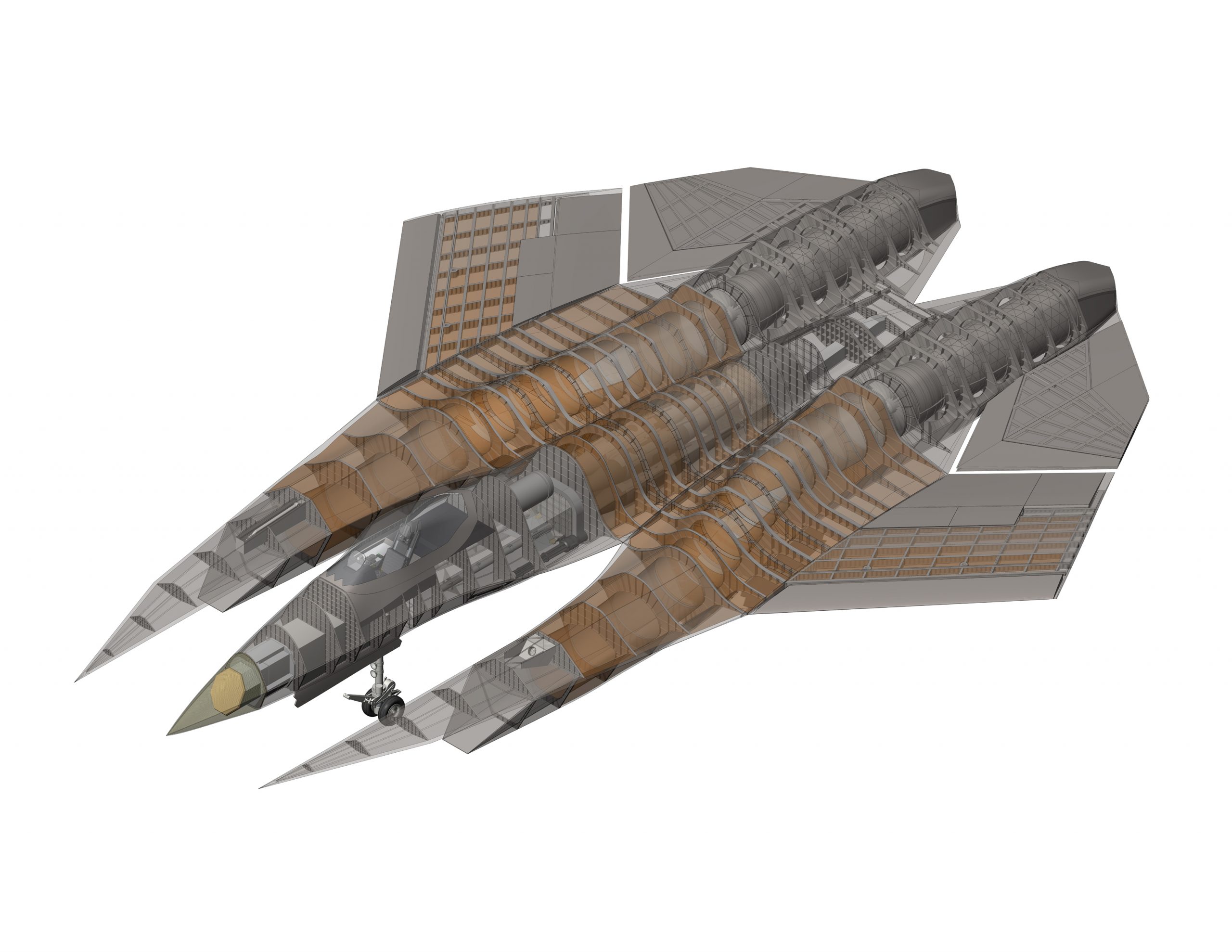
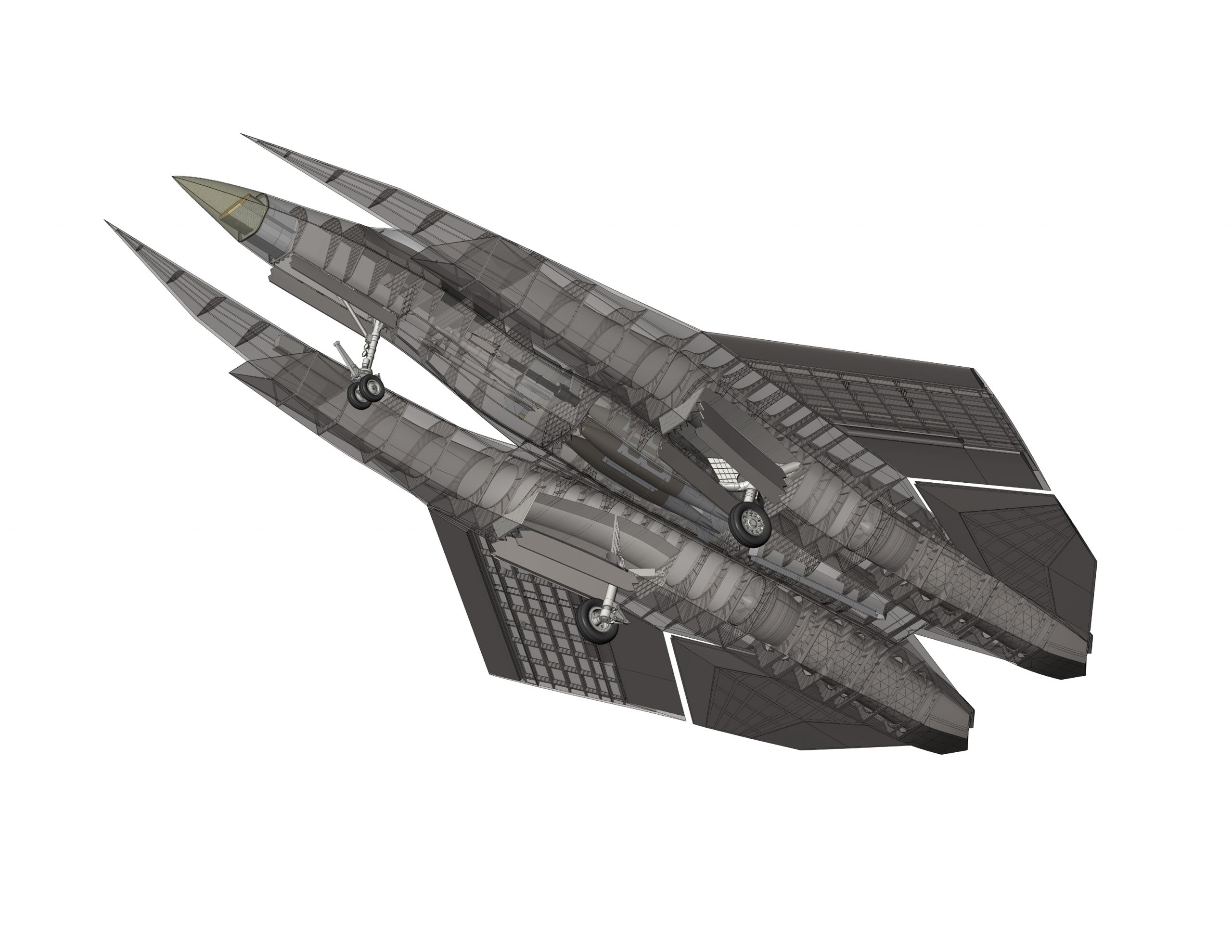
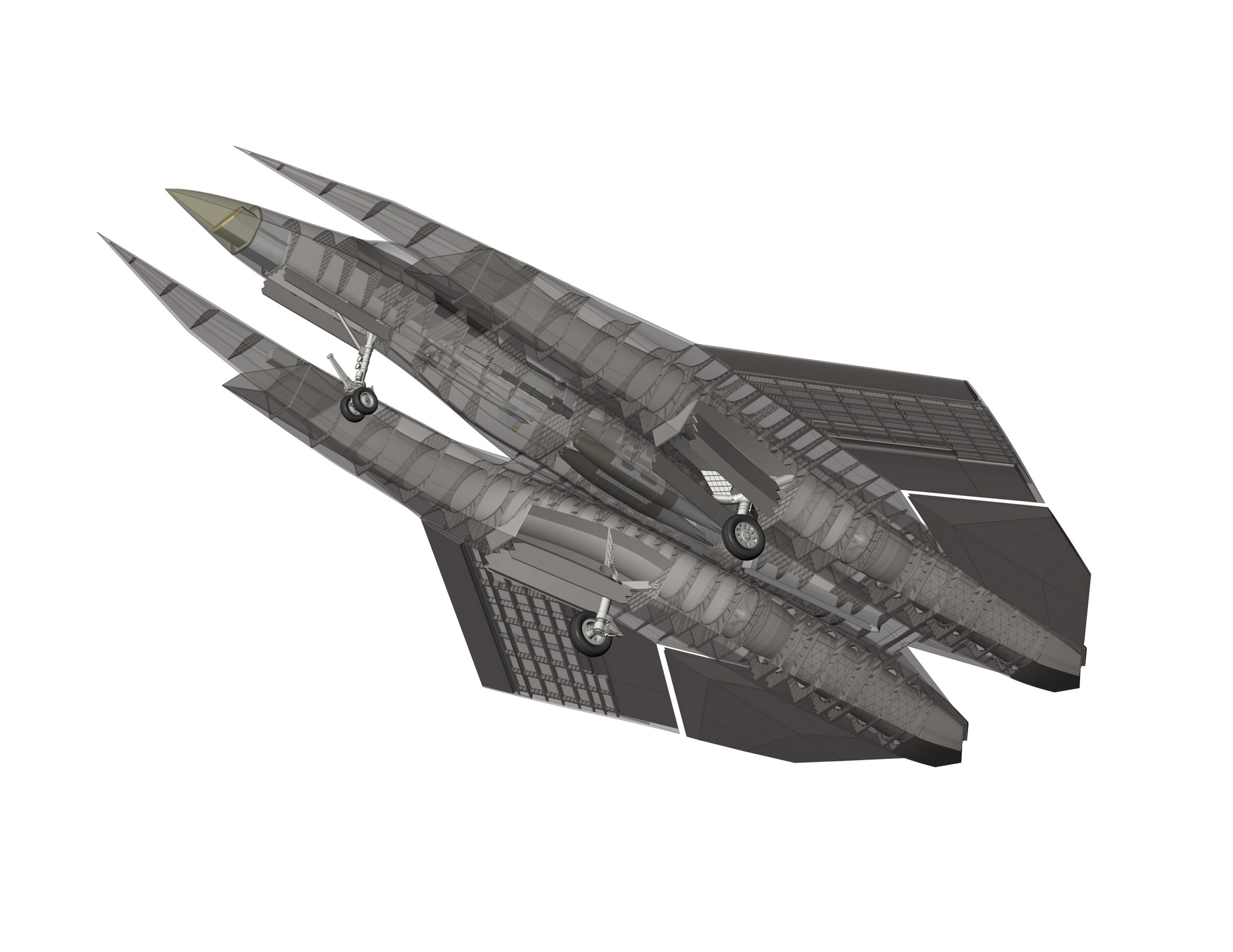
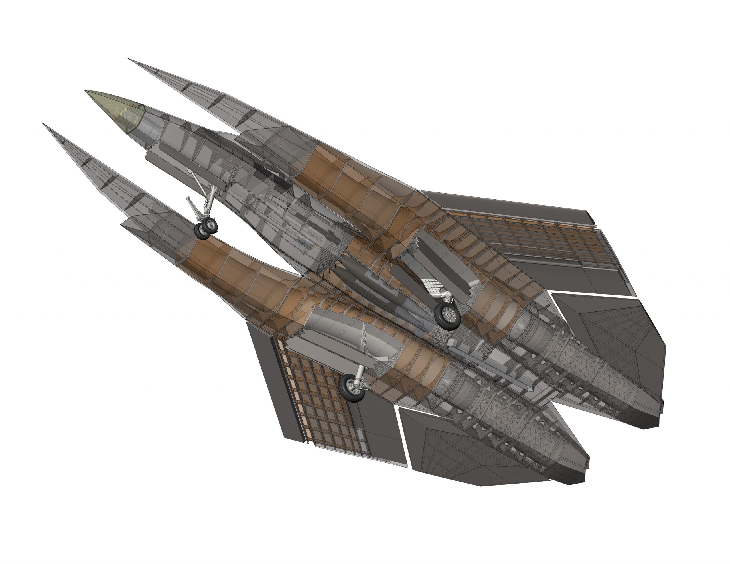
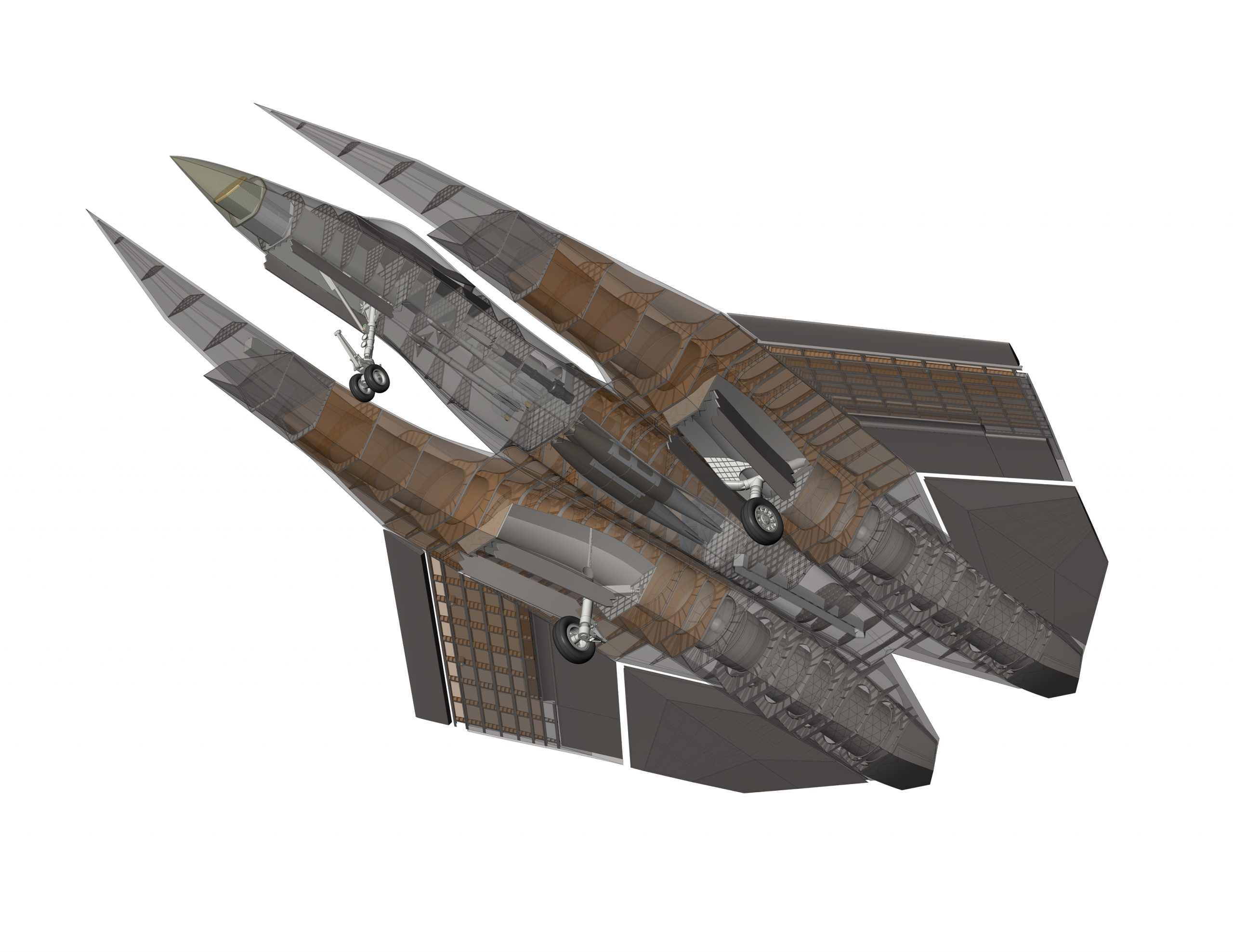
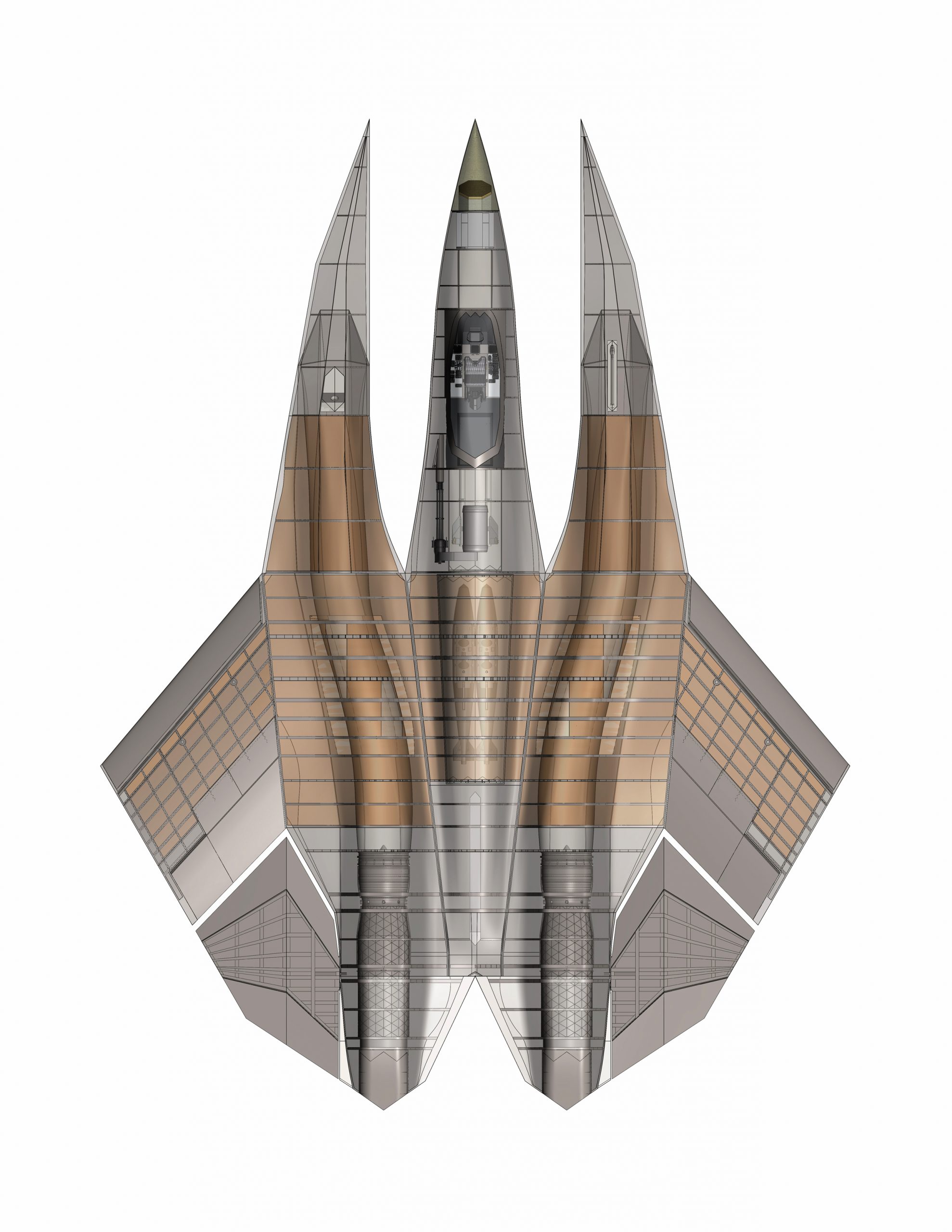
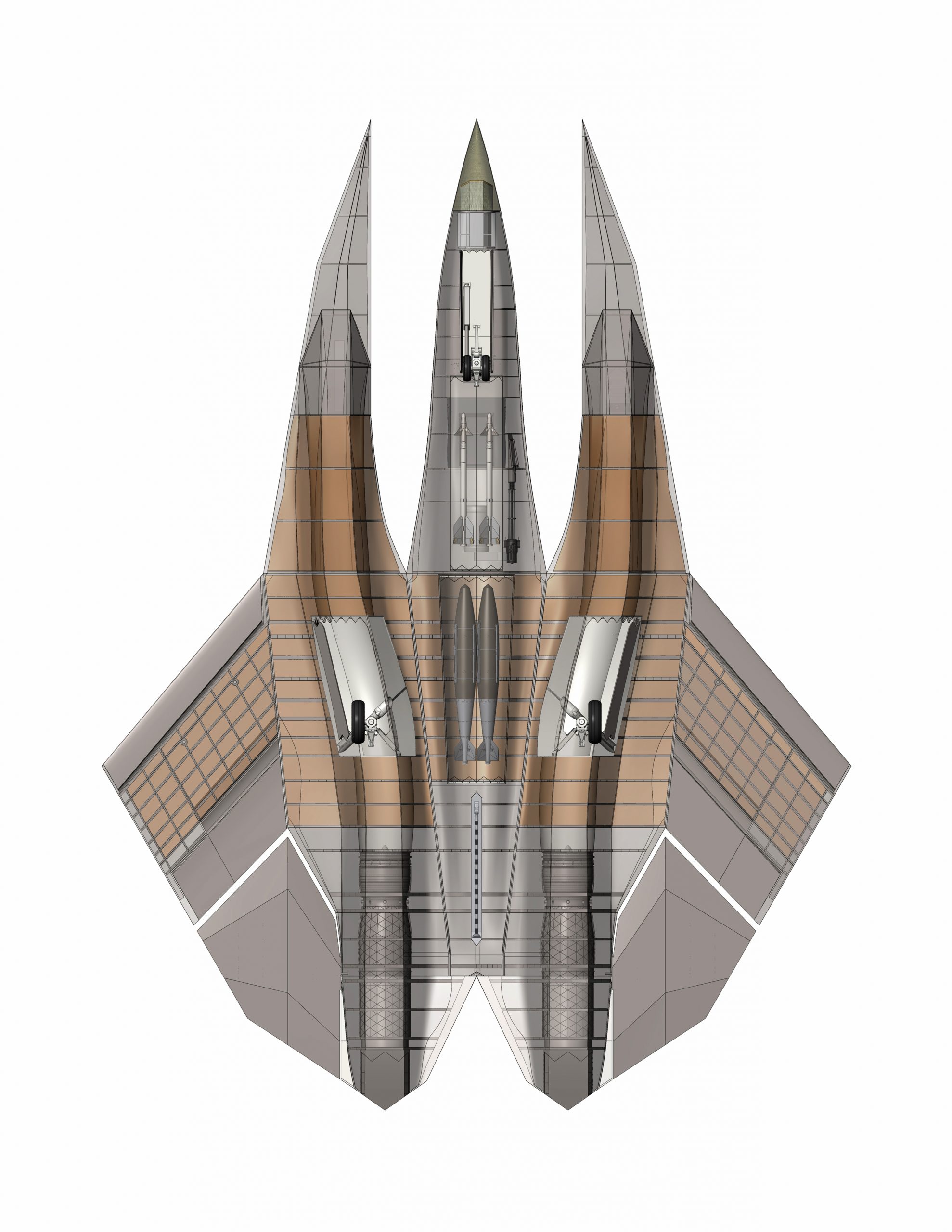
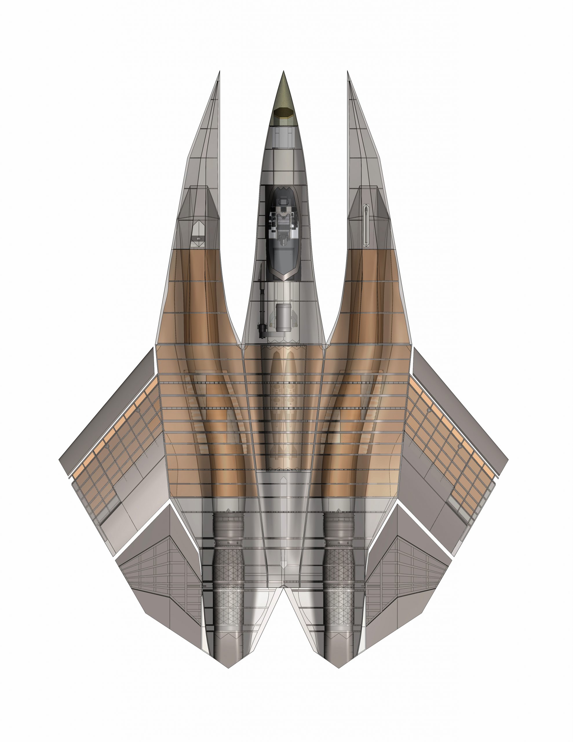
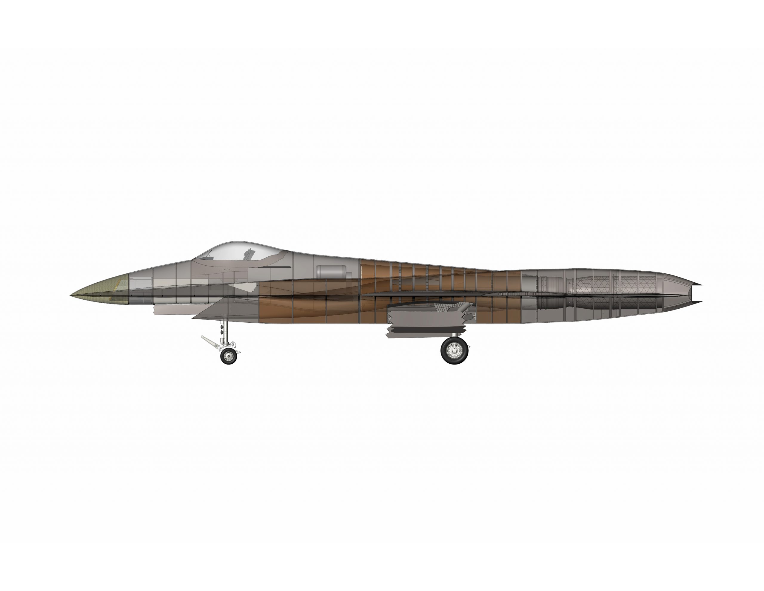
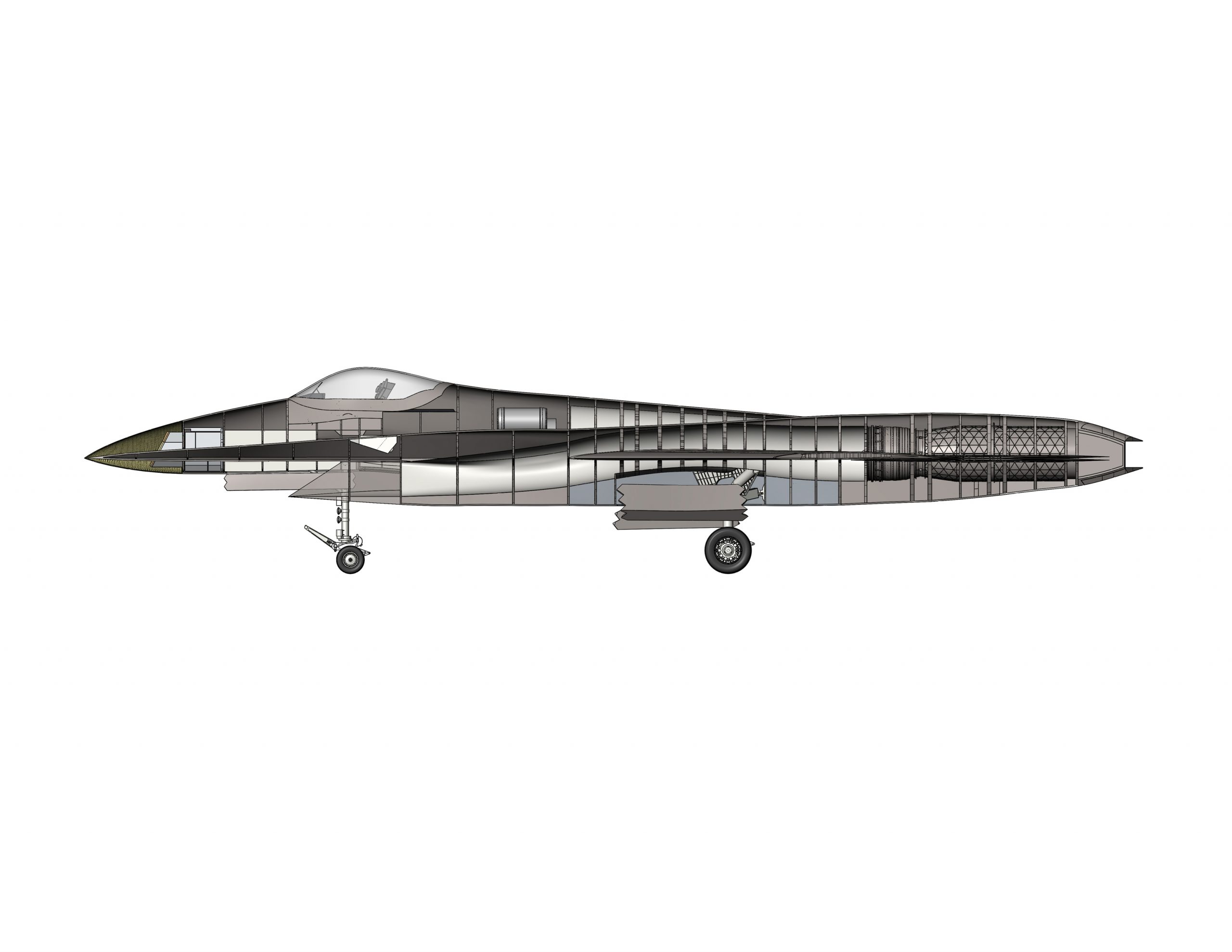